
Rocket engine chamber with layered internal wall channels

a technology of internal wall channels and rocket engines, which is applied in the direction of rocket engine plants, machines/engines, cosmonautic vehicles, etc., can solve the problems of limited heat transfer efficiency, inefficient use of coolant, and relatively high pressure drop of coolant through the channel, so as to achieve small cross section, reduce pressure drop in the inner channel, and reduce the effect of heat loss

Inactive Publication Date: 2008-03-18
AEROJET ROCKETDYNE INC
View PDF6 Cites 15 Cited by
  • Summary
  • Abstract
  • Description
  • Claims
  • Application Information

AI Technical Summary

Benefits of technology

This solution achieves a higher cooling efficiency with lower pressure drops, cooler metal walls, extended component life, and reduced weight by optimizing coolant distribution and channel design, enhancing the performance and durability of rocket engines.

Problems solved by technology

Channels running in this direction limit the efficiency of the heat transfer for several reasons.
First, channels that extend the full length of the nozzle cause the coolant to undergo a relatively high pressure drop through the channel due to the length of the channel and the friction at the channel wall.
Third, the heat generated in the combustion chamber (generally the subsonic) section of the assembly is much greater than the heat generated in the skirt (generally the supersonic) section, and yet the total volumetric flow rate of coolant is the same in both sections, resulting in inefficient use of the coolant.
With these inefficiencies, the temperature of the metal in the nozzle wall remains high and the useful life of the chamber / nozzle is relatively short.
Furthermore, to accommodate coolant channels that are large enough to carry the volume of coolant needed to cool both sections of the chamber / nozzle, the jacket and hence the entire wall must be relatively thick which adds considerably to the weight of the assembly.

Method used


Image

  • Rocket engine chamber with layered internal wall channels
  • Rocket engine chamber with layered internal wall channels
  • Rocket engine chamber with layered internal wall channels

Examples


Embodiment Construction

[0019]As the summary above suggests, this invention is capable of implementation in a variety of ways. The invention and its scope can be readily understood however by a detailed examination of specific embodiments. One such embodiment is shown in the drawings and described below.

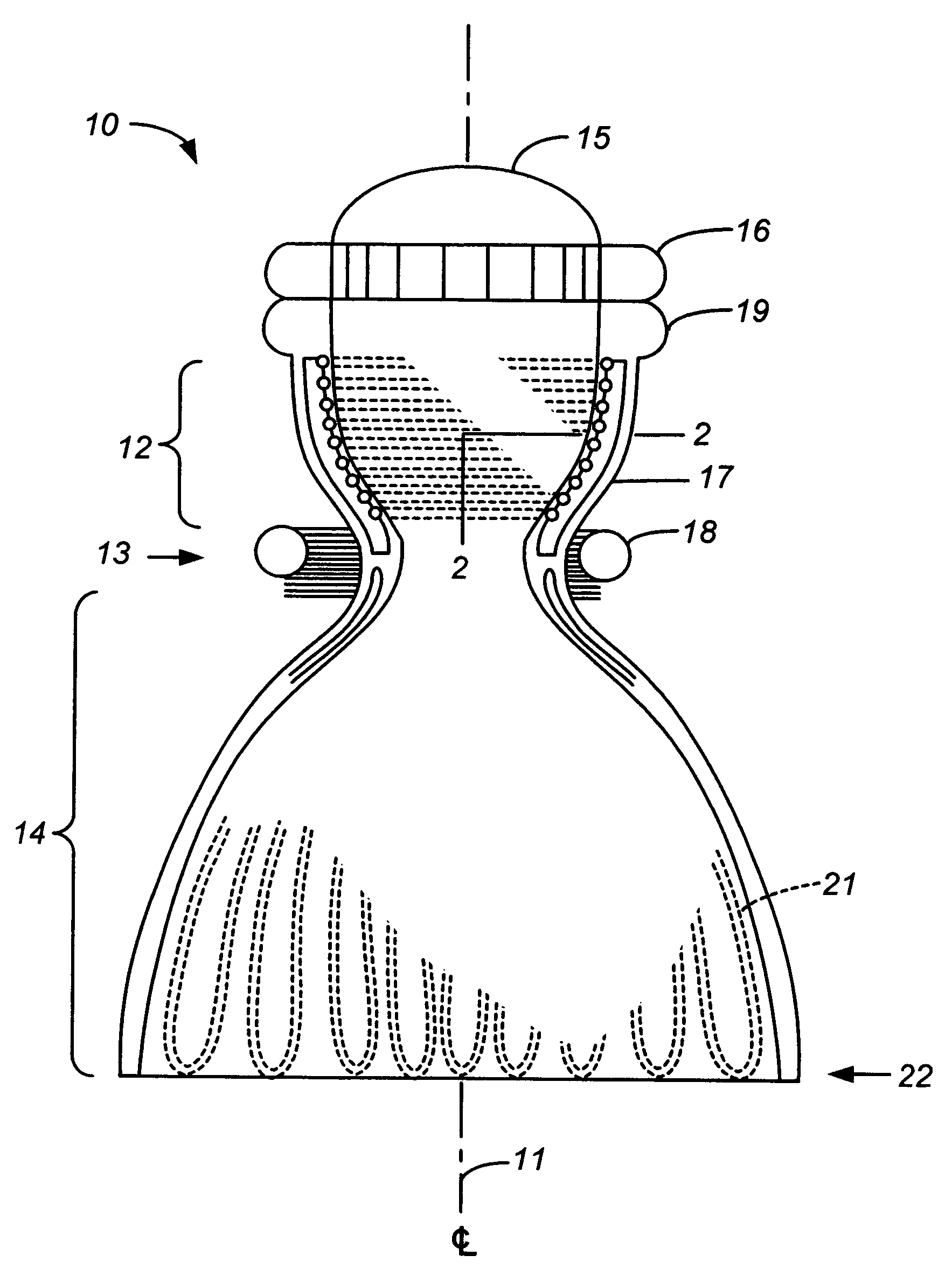
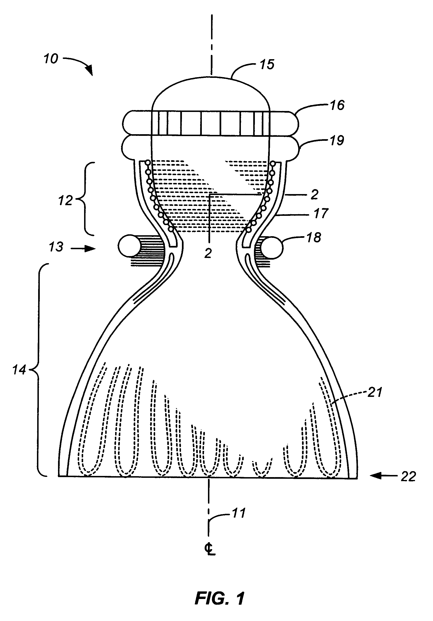
[0020]A chamber / throat / nozzle assembly that contains the features of the present invention is shown in cross section in FIG. 1. The chamber / nozzle assembly 10 is a body of revolution around a centerline 11 and the cross section is a plane that includes the centerline. The assembly 10 includes a convergent section or chamber 12, a throat 13, and a divergent section 14. Although the assembly is shown with a curved profile with a smoothly curved throat and a large nozzle (divergent section) relative to the chamber, the assembly may alternatively have the shape of two truncated cones both tapering toward and joined at the throat plane, with a sharp-angled throat, or with a chamber that is longer than the nozzle...


PUM


Abstract

A combustion chamber / supersonic nozzle assembly is cooled by an array of coolant channels in the wall of the assembly with coolant being fed to the assembly at the throat plane between the subsonic (convergent) and supersonic (divergent) sections. A minor portion of the coolant entering at the throat plane is directed to coolant channels in the supersonic section wall, while the remainder is directed to a complex arrangement of channels in the subsonic section wall. The latter arrangement includes an outer layer of wide axially oriented channels for delivery of coolant to, and removal from, an inner layer of smaller, circumferentially oriented channels that are adjacent to the hot gas and carry the bulk of the coolant load. The path of coolant travel through each inner channel is relatively short, lessening the pressure drop through those channels relative to coolant channel arrangements of the prior art.

Description

CROSS-REFERENCE TO RELATED APPLICATIONS[0001]This application is related to U.S. Provisional Patent Application No. 60 / 452,287, filed Mar. 4, 2003, and claims all benefits legally capable of being offered by the provisional patent application. The entire contents of the provisional patent application are incorporated herein by reference.BACKGROUND OF THE INVENTION[0002]1. Field of the Invention[0003]This invention resides in the field of rocket engine design, with particular applicability to heat exchange structures for rocket chambers and nozzles.[0004]2. Description of the Prior Art[0005]Rocket engines generally require a durable construction that can withstand extreme conditions of temperature and pressure encountered during both takeoff and flight. Extreme conditions are also encountered by other types of equipment, such as hypersonic vehicle surfaces, missile nose tips, radar domes, and the like. Using rocket engines as examples, those for which structural durability is most cr...

Claims


Application Information

Patent Timeline
Patent Type & Authority Patents(United States)
IPC IPC(8): F02K9/64
CPCF02K9/64F02K9/972B64G1/401
Inventor HEWITT, ROSS A.
Owner AEROJET ROCKETDYNE INC
Learn More