Intake device and mounting structure of valve unit
a technology of valve unit and mounting structure, which is applied in the direction of air intake for fuel, machines/engines, combustion air/fuel air treatment, etc., can solve the problems of deteriorating engine performance, affecting the performance of the engine, and the valve member is likely to leak through the gap, so as to reduce the displacement of the axes of the valve member among the plural valve units , the effect of not increasing the torque of the sha
- Summary
- Abstract
- Description
- Claims
- Application Information
AI Technical Summary
Benefits of technology
Problems solved by technology
Method used
Image
Examples
first example embodiment
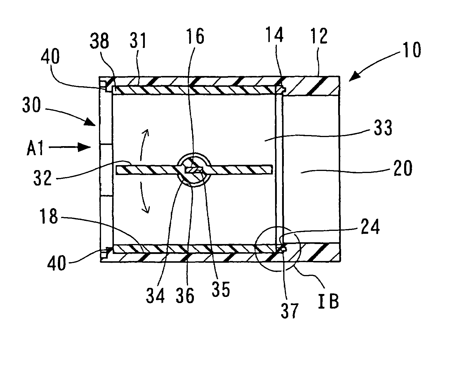
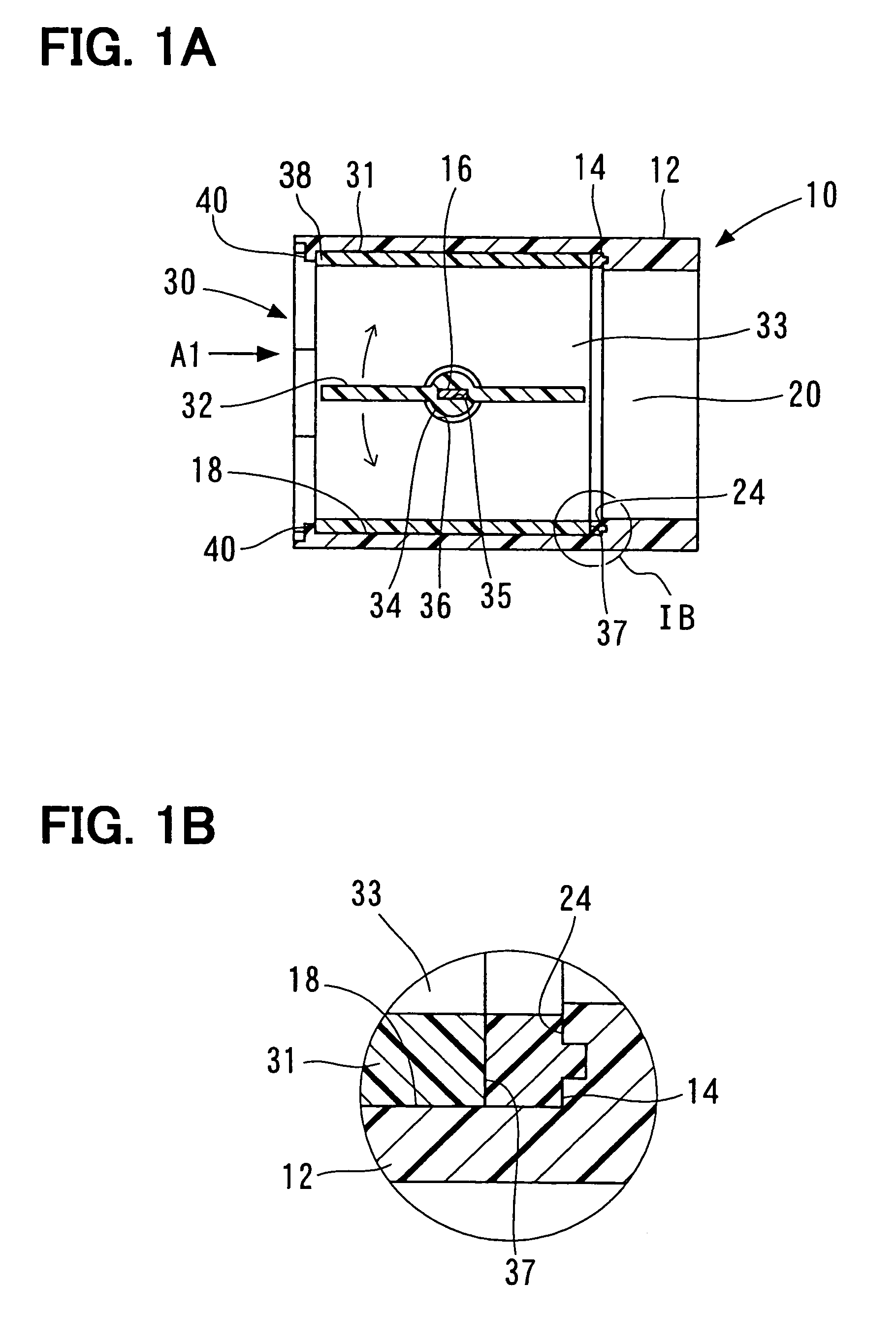
[0027]A first example embodiment of an intake device will be described with reference to FIGS. 1A to 5B. Although not illustrated, an intake device 10 shown in FIGS. 1A to 3 is for example disposed between a surge tank and an intake manifold. For example, intake air having passed through an air cleaner is drawn in the non-illustrated surge tank. The intake air flows from the surge tank into the non-illustrated intake manifold through the intake device 10. In FIG. 1, an arrow A1 denotes a flow direction of the intake air.
[0028]The non-illustrated intake manifold has plural intake air passages having different lengths. The intake device 10 distributes the intake air into the air intake passages of the non-illustrated intake manifold.
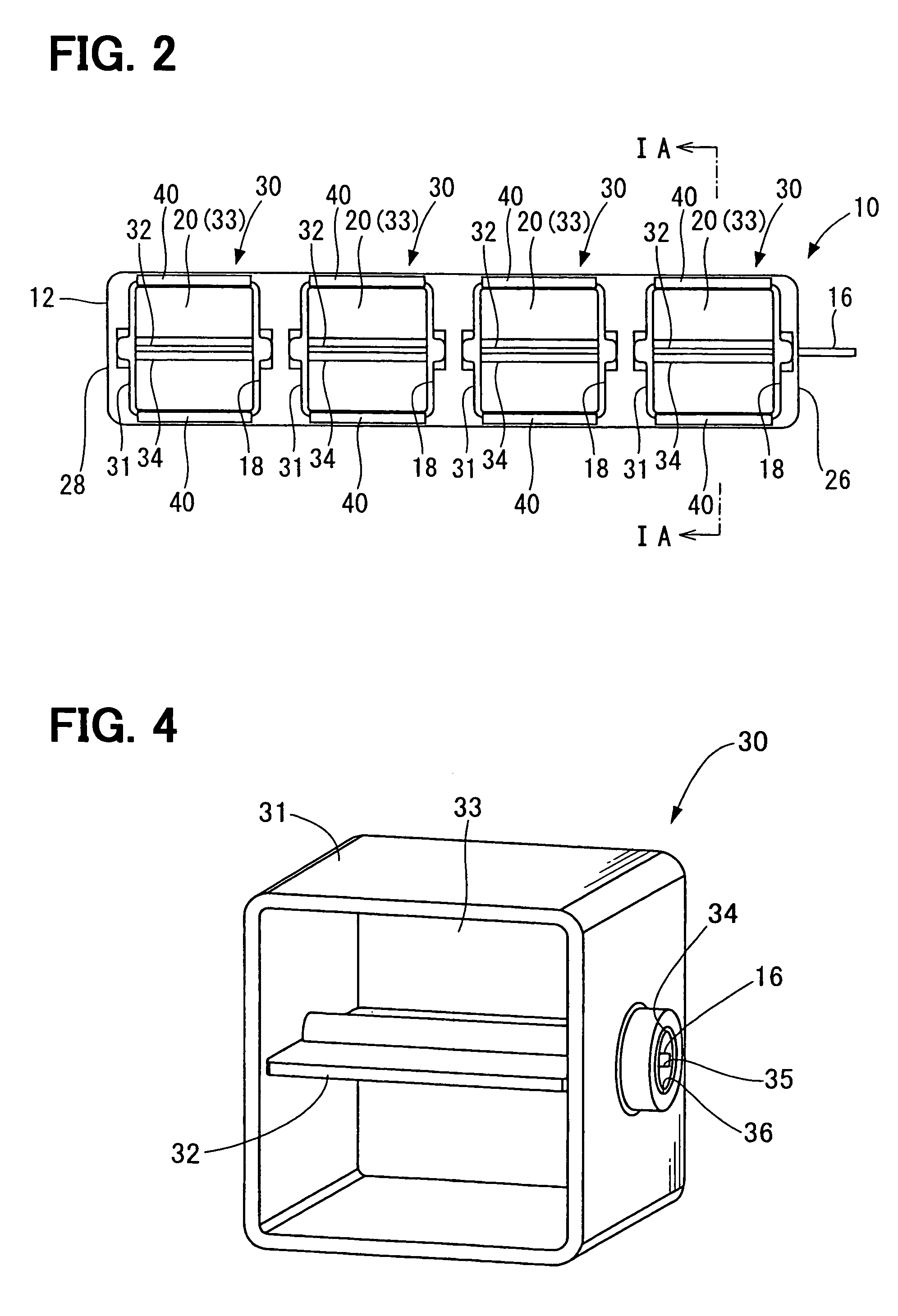
[0029]As shown in FIGS. 1A to 3, the intake device 10 has an intake manifold 12, valve units 30, sealing members 14 as deformed members, and a shaft 16. The intake manifold 12 is made of resin and forms plural housing chambers 18. Each of the housing chamb...
second example embodiment
[0054]A second example embodiment of the intake device 10 will be described with reference to FIGS. 6A, 6B and 7. Here, like components are denoted by like reference characters and a description thereof is not repeated. As shown in FIGS. 6A, 6B and 7, the intake device 10 has a cover plate 50, in place of the fixing portions 40 of the first example embodiment.
[0055]The cover plate 50 is disposed on an upstream end surface of the intake manifold 12, which is on a side opposite to the sealing member 14. The cover plate 50 has openings 51. Each of the openings 51 has a shape corresponding to the shape of each housing chamber 18 of the intake manifold 12. The cover plate 50 is made of resin. The cover plate 50 is fixed to the intake manifold 12 such as by thermal adhesion or welding.
[0056]Further, the cover plate 50 is fixed to the intake manifold 12 such that the upstream end 38 of each valve unit 30, which is on a side opposite to the sealing member 14, contacts the cover plate 50. Si...
PUM
| Property | Measurement | Unit |
|---|---|---|
| shapes | aaaaa | aaaaa |
| shape | aaaaa | aaaaa |
| torque | aaaaa | aaaaa |
Abstract
Description
Claims
Application Information
 - R&D
- Intellectual Property
- Life Sciences
- Materials
- Tech Scout
- Unparalleled Data Quality
- Higher Quality Content
- 60% Fewer Hallucinations
Browse by: Latest US Patents, China's latest patents, Technical Efficacy Thesaurus, Application Domain, Technology Topic, Popular Technical Reports.
© 2025 PatSnap. All rights reserved.Legal|Privacy policy|Modern Slavery Act Transparency Statement|Sitemap|About US| Contact US: help@patsnap.com


