Electromagnetic wave shield

a shield and electromagnetic technology, applied in shielding materials, discharge tubes/lamp details, lamp incadescent bodies, etc., can solve the problems of extreme reduction in communication distance, short communication distance, and reduced electric field, so as to suppress the attenuation of magnetic near field, effectively use the magnetic near field, and effectively attenuate the electric far field

Active Publication Date: 2008-03-04
PANASONIC CORP
View PDF36 Cites 30 Cited by
  • Summary
  • Abstract
  • Description
  • Claims
  • Application Information

AI Technical Summary

Benefits of technology

[0010]According to the electromagnetic wave shield in accordance with the invention, the magnetic coupling of the magnetic flux of the electromagnetic wave discharged from a high frequency electromagnetic wave generator and the electromagnetic wave shield can be reduced. Therefore, it is possible to provide an electromagnetic wave shield capable of attenuating a electric far field while suppressing the 5 attenuation of a vicinal magnetic flux. By using the electromagnetic wave shield according to the invention, mainly, it is possible to attenuate the electric far field while suppressing the attenuation of the vicinal magnetic flux as countermeasures against the unnecessary radiation of high frequency applying apparatuses such as a high frequency heater, a non-electrode discharge lamp and a communicating device which mainly utilize the vicinal magnetic flux for their operations. Consequently, it is possible to effectively utilize the vicinal magnetic flux generated from a high frequency electromagnetic wave generator.
[0012]According to the electromagnetic wave shield in accordance with the invention, the magnetic coupling of the magnetic field of the electromagnetic wave discharged from a high frequency electromagnetic wave, generator and the electromagnetic wave shield can be reduced. Therefore, it is possible to provide an electromagnetic wave shield capable of attenuating a electric far field while suppressing the attenuation of a magnetic near field. By using the electromagnetic wave shield according to the invention, it is possible to attenuate the electric far field while suppressing the attenuation of the vicinal magnetic flux as countermeasures against the unnecessary radiation of high frequency applying apparatuses such as a high frequency heater, a non-electrode discharge lamp and a communicating device which mainly utilize the magnetic near field for their operations. Consequently, it is possible to effectively utilize the magnetic near field generated from the high frequency electromagnetic wave generator.
[0014]According to the electromagnetic wave shield in accordance with the invention, the magnetic coupling of the magnetic field of the electromagnetic wave discharged from a high frequency electromagnetic wave generator and the electromagnetic wave shield can be reduced. Therefore, it is possible to provide an electromagnetic wave shield capable of attenuating a electric far field while suppressing the attenuation of a magnetic near field. By using the electromagnetic wave shield according to the invention, it is possible to attenuate the electric far field while suppressing the attenuation of the vicinal magnetic flux as countermeasures against the unnecessary radiation of high frequency applying apparatuses such as a high frequency heater, a nonelectrode discharge lamp and a communicating device which mainly utilize the magnetic near field for their operations. Consequently, it is possible to effectively utilize the magnetic near field generated from the high frequency electromagnetic wave generator.
[0015]The invention provides an electromagnetic wave shield comprising a plurality of electric conductors, a ground contact for carrying out a connection to a ground, and a lead wire for connecting the electric conductors to the ground contact, the electric conductors being electrically connected to the ground contact through the lead wire, wherein a wire width of each of the electric conductors ranges from 0.05 mm to 5 mm, and an average interval between the electric conductors which is obtained by dividing a length of a side on which the electric conductors and an outer periphery of a region provided with the electric conductors cross each other by a number of points on which the electric conductors and the outer periphery of the region provided with the electric conductors cross each other ranges from 4 mm to 50 mm. Therefore, the magnetic coupling of the magnetic near field of the electromagnetic wave discharged from a high frequency electromagnetic wave generator and the electromagnetic wave shield can be reduced. Therefore, it is possible to provide an electromagnetic wave shield capable of attenuating a electric far field while suppressing the attenuation of the magnetic near field. By using the electromagnetic wave shield according to the invention, it is possible to attenuate the electric far field while suppressing the attenuation of the vicinal magnetic flux as countermeasures against the unnecessary radiation of high frequency applying apparatuses such as a high frequency heater, a non-electrode discharge lamp and a communicating device which mainly utilize the magnetic near field for their operations. Consequently, it is possible to effectively utilize the magnetic near field generated from the high frequency electromagnetic wave generator.
[0018]According to the invention, it is possible to effectively attenuate the electric far field which is radiated from the high frequency electromagnetic wave generator or the loop antenna apparatus and becomes an unnecessary radiation while suppressing the attenuation of the magnetic near field. Consequently, it is possible to provide a high frequency electromagnetic wave generator and a loop antenna apparatus which can satisfy the regulation of the unnecessary radiation and can effectively use the magnetic near field.

Problems solved by technology

In this case, however, there is a problem in that a communication distance is shortened.
In these conventional structures, however, there is a problem in that the electric field can be decreased and the attenuation of a vicinal magnetic flux required for the communication is also increased, resulting in an extreme reduction in a communication distance.

Method used


Image

  • Electromagnetic wave shield
  • Electromagnetic wave shield
  • Electromagnetic wave shield

Examples


first embodiment

(First Embodiment)

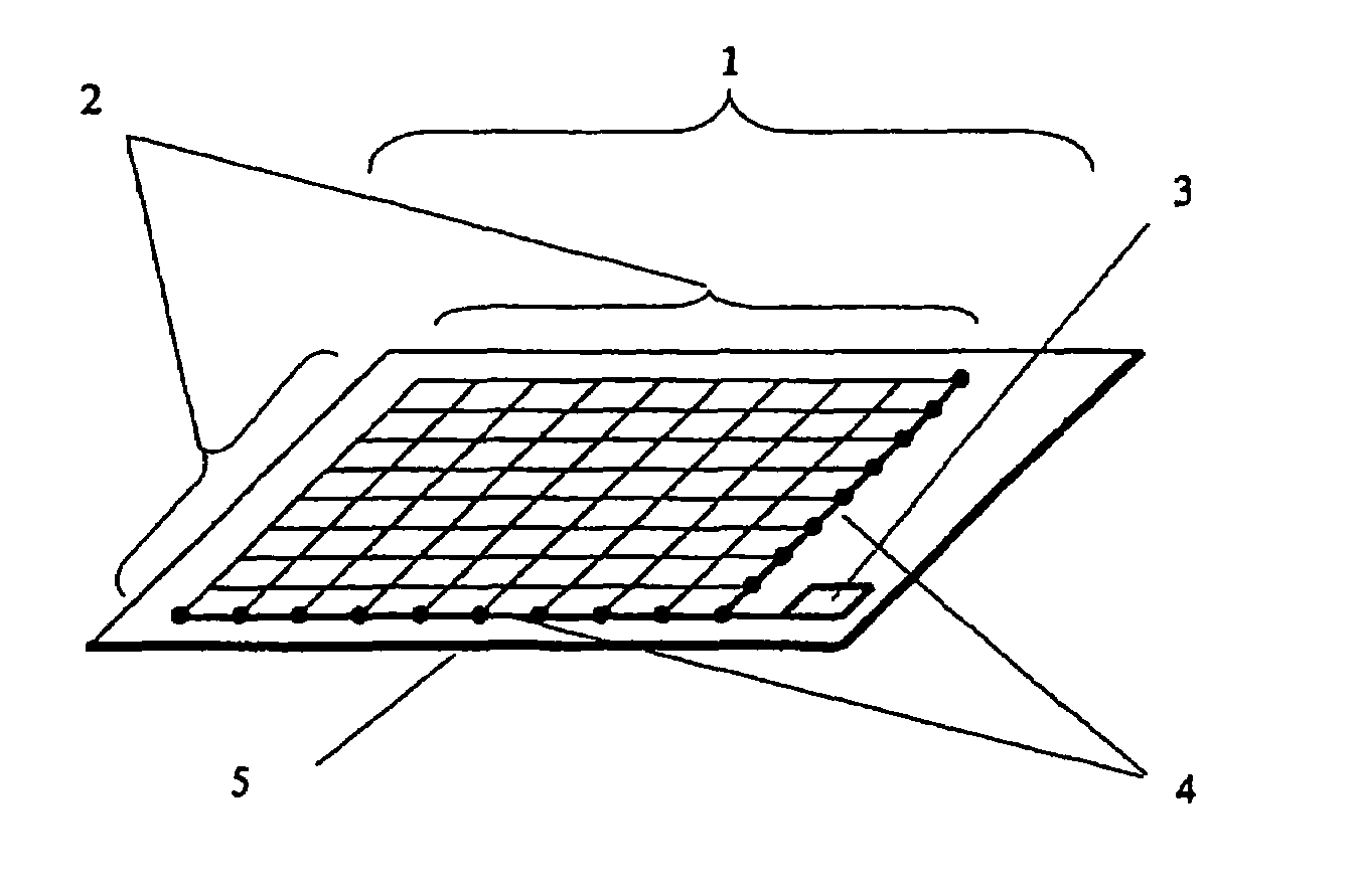
[0057]FIG. 1 shows an electromagnetic wave shield according to a first embodiment as an embodiment of the invention; FIG. 1 is a schematic perspective view showing an electromagnetic wave shield according to the first embodiment of the invention.

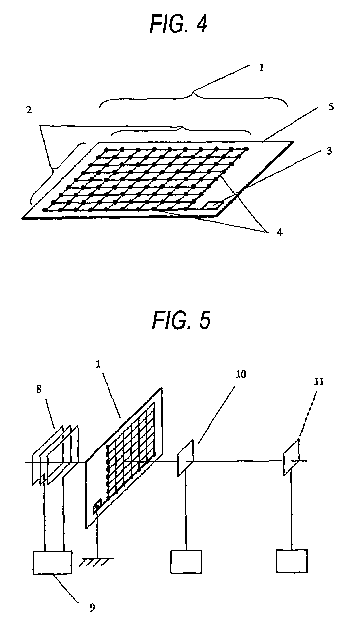
[0058]As shown in FIG. 1, an electromagnetic wave shield 1 is constituted by a plurality of electric conductors 2, a ground contact 3 for grounding the electric conductors 2, a lead wire 4 for connecting the electric conductors 2 to the ground contact 3, and a support member 5 for holding the electric conductors 2, the ground contact 3 and the lead wire 4. The electric conductors 2 are mesh-shaped or grid-shaped. A black circle mark in the drawing indicates that an electrical connection is carried out between the electric conductors 2. In a part in which the electric conductors 2 cross each other, accordingly, a portion having no black circle mark indicates that they are not electrically connected to each other but are insu...

second embodiment

(Second Embodiment)

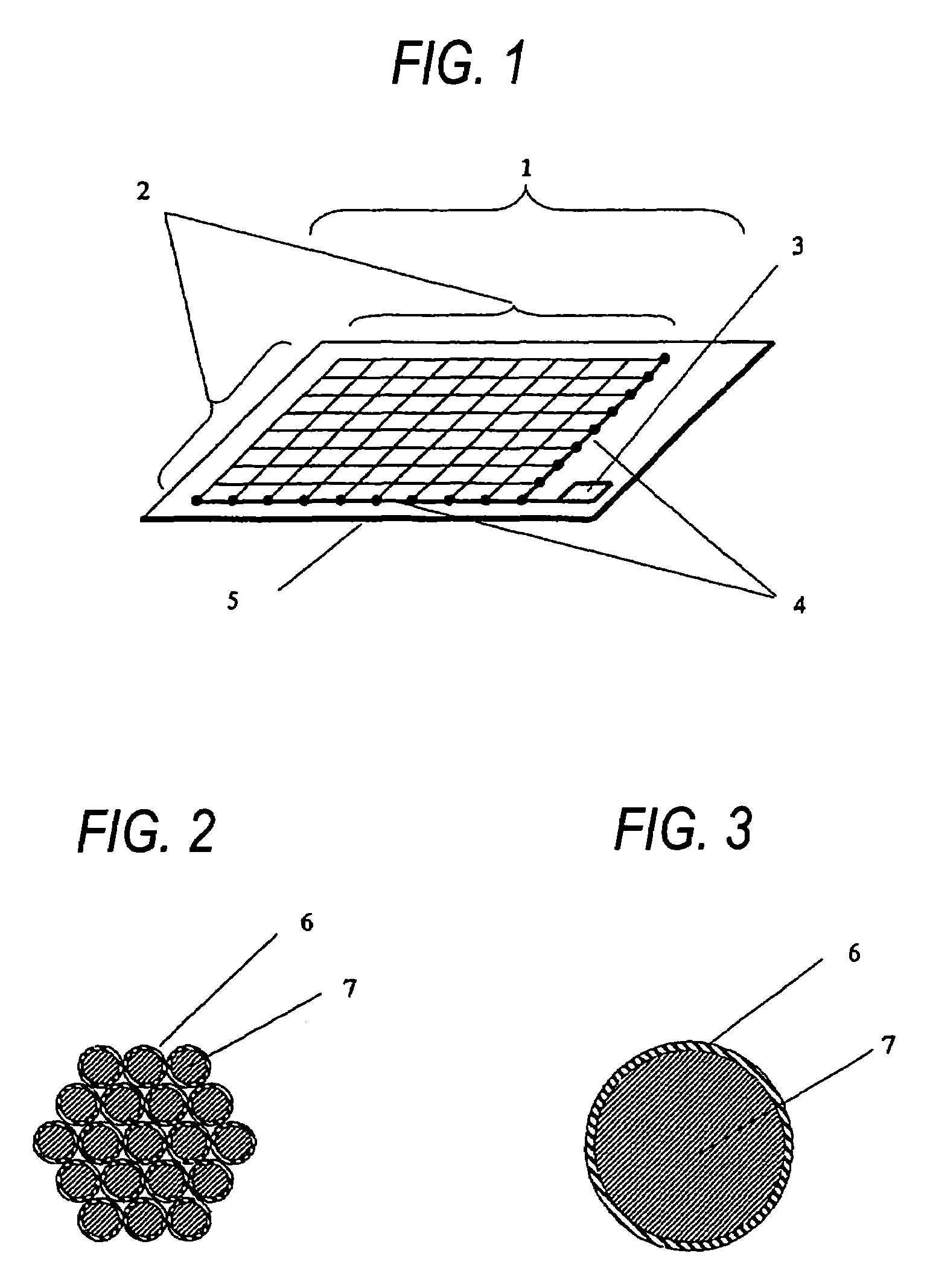
[0061]While the litz wires are used for the electric conductors 2 in the first embodiment, a solid wire of copper having an almost equal sectional area to that in the first embodiment is used to fabricate an electromagnetic wave shield 1 in a second embodiment. The electromagnetic wave shield takes almost the same shape as that shown in FIG. 1 according to the first embodiment and only the electric conductors 2 are different.

[0062]FIG. 3 is a sectional view showing an electric conductor according to the second embodiment of the invention. As shown in FIG. 3, a solid wire to be used is constituted by an insulating cover 6 and a copper member 7.

[0063]In the same manner as in the first embodiment, a plurality of electric conductors 2 come in electrical contact with a lead wire 4 connected to a ground contact 3 in one place respectively in the second embodiment. As seen electrically, it is indicated that a path is uniquely determined when following the electric conduc...

third embodiment

(Third Embodiment)

[0087]An electromagnetic wave is usually discharged three-dimensionally. In the case in which an unnecessary electromagnetic wave is to be shielded, therefore, it is necessary to three-dimensionally shield a source for generating an electromagnetic wave. An electromagnetic wave shield 1 according to a third embodiment can solve the problem by employing a structure in which the source for generating an electromagnetic wave is covered.

[0088]FIG. 11 shows the electromagnetic wave shield 1 according to the third embodiment. FIG. 11 is a schematic perspective view showing the electromagnetic wave shield according to the third embodiment of the invention. The electromagnetic wave shield 1 according to the third embodiment is constituted by a plurality of electric conductors 2, a ground contact 3 for grounding the electric conductors 2, a lead wire 4 for connecting the electric conductors 2 to the ground contact 3, and a box-shaped support member 5 for holding the electri...


PUM


Abstract

It is an object of the invention to provide an electromagnetic wave shield for attenuating a electric far field while suppressing the attenuation of the vicinal magnetic flux of an electromagnetic wave discharged from a high frequency electromagnetic wave generator.An electromagnetic wave shield according to the invention comprises a plurality of electric conductors, a ground contact for carrying out a connection to a ground, and a lead wire for connecting the electric conductors to the ground contact, the electric conductors being electrically connected to the ground contact through the lead wire, wherein the electric conductors are provided in such a manner that a path reaching the ground contact through the lead wire from an optional point of each of the electric conductors is uniquely determined.

Description

BACKGROUND OF THE INVENTION[0001]1. Field of the Invention[0002]The present invention relates to an electromagnetic wave shield to be used in an apparatus applying a high frequency electromagnetic field.[0003]2. Description of the Related Art[0004]Equipment applying a high frequency electromagnetic field has been utilized in a variety of fields, for example, a cooking device using induction heating, a fixing component for a laser printer, a discharge lamp using a plasma induced by an induction field or a communicating device for transferring an energy in non-contact which uses an induction field. In an information terminal such as a computer including a cell phone, moreover, the influence of an electromagnetic wave radiated secondarily from the electronic equipment cannot be disregarded due to a rapid increase in a radio information transmission or a further increase in a driving frequency, and the regulation of an unnecessary radiation, that is, the regulation of the discharge of a...

Claims


Application Information

Patent Timeline
Patent Type & Authority Patents(United States)
IPC IPC(8): H05K9/00
CPCH05K9/009
Inventor NOTOHARA, YASUHIROKANEKO, SHINICHIROUDEGUCHI, FUTOSHIYOSHINAGA, HIROSHISHIMIZU, SHOICHI
Owner PANASONIC CORP
Why Eureka
Try Eureka