Ultrasonic scatterer, ultrasonic imaging method and ultrasonic imaging apparatus
a ultrasonic imaging and ultrasonic imaging technology, applied in the field of ultrasonic scatterers, ultrasonic imaging methods and ultrasonic imaging apparatus, can solve the problems of inability to singly detect sub-harmonics in blood vessels, inability to detect sub-harmonics singly, and failure of micro balloons, etc., to achieve excellent space resolution
- Summary
- Abstract
- Description
- Claims
- Application Information
AI Technical Summary
Benefits of technology
Problems solved by technology
Method used
Image

Examples
first embodiment
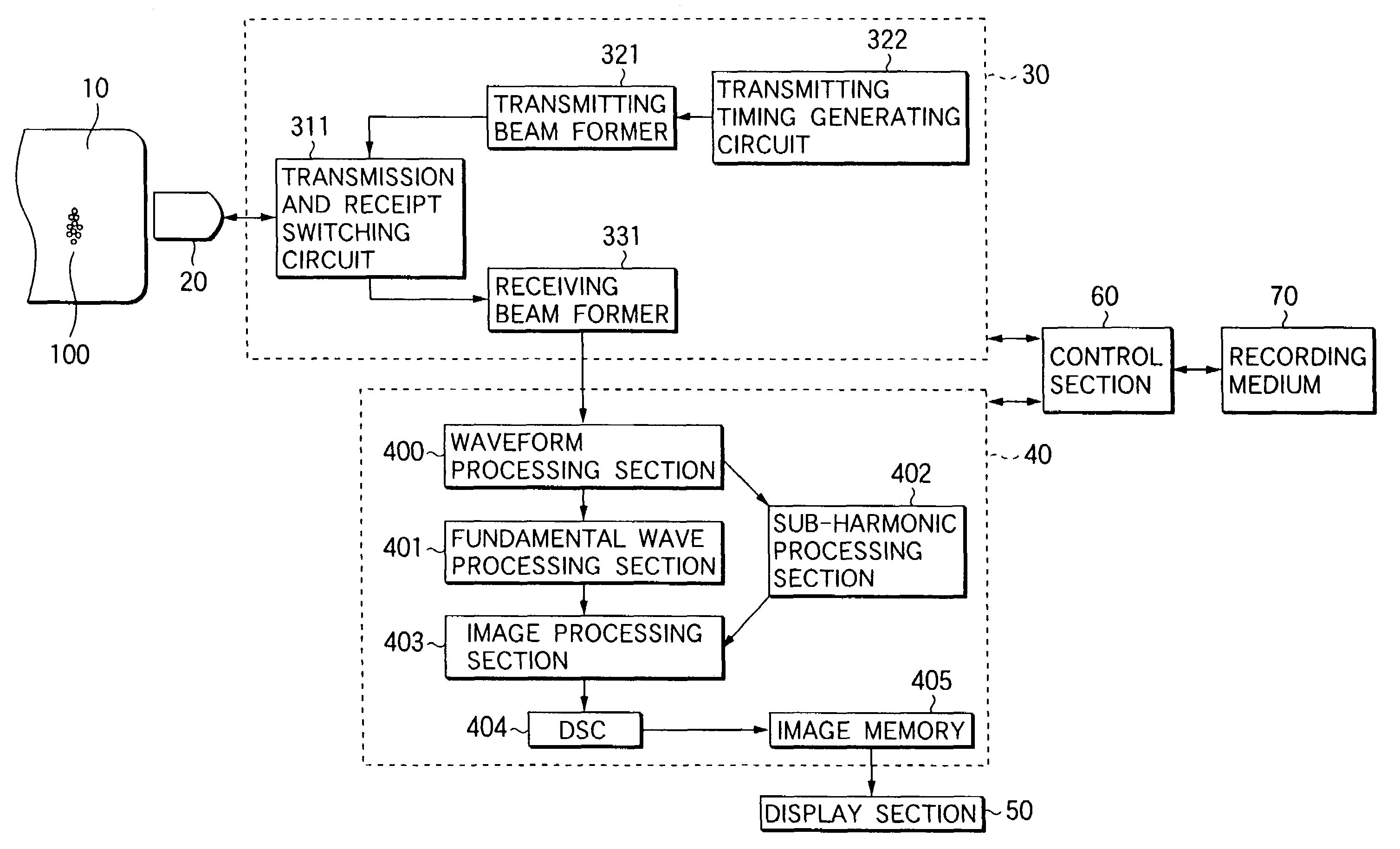
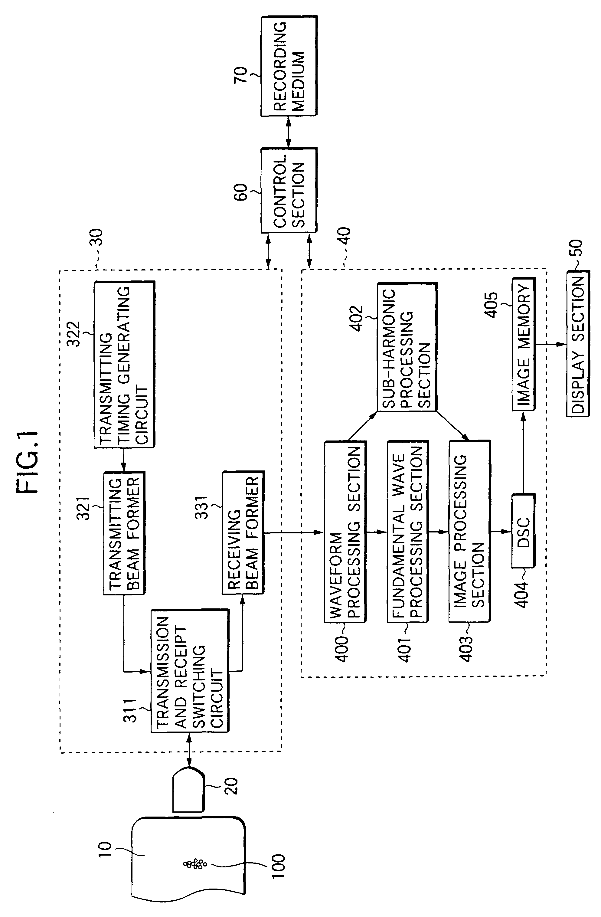
[0139]FIG. 1 is a block diagram showing the structure of an ultrasonic imaging apparatus according to the invention.
[0140]As shown in FIG. 1, the ultrasonic imaging apparatus comprises an ultrasonic probe 20 including an ultrasonic transducer array constituted by a plurality of ultrasonic transducers. The ultrasonic probe 20 is used in abutment on a subject 10 by an operator. By previous injection of a micro bubble contrast agent, the subject 10 includes a micro bubble 100.
[0141]The ultrasonic probe 20 is connected to a transmitting and receiving section 30. In the transmitting and receiving section 30, a transmitting timing generating circuit 322 periodically generates a transmitting timing signal and sends the transmitting timing signal to a transmitting beam former 321. The transmitting beam former 321 generates a plurality of driving signals (transmitting beam forming signals) for driving a plurality of ultrasonic transducers of the ultrasonic probe 20 with a time difference bas...
second embodiment
[0176]Furthermore, the receiving beam former 331 may give a time difference to a plurality of received echoes to adjust a phase, and may then add them to form an echo detection signal along a sound ray, that is, to carry out the beam forming of a received wave. The receiving beam former 331 processes the detection signals S1 and S2 to finally output a first detection signal R1 and a second detection signal R2 which have phases shifted by a time equivalent to one cycle of a transmitted ultrasonic wave. In a waveform processing section 400, a difference between the first detection signal R1 and the second detection signal R2 is obtained, thereby acquiring a waveform RSUB of the sub-harmonic signal shown in FIG. 8 in the same manner as in the
[0177]While the example in which the sub-harmonic echo is utilized to carry out B mode imaging has been described in these embodiments, ultrasonic imaging is not restricted to the B mode imaging but a Doppler shift of a sub-harmonic echo maybe util...
PUM
| Property | Measurement | Unit |
|---|---|---|
| average particle size | aaaaa | aaaaa |
| particle size | aaaaa | aaaaa |
| center-to-center distance | aaaaa | aaaaa |
Abstract
Description
Claims
Application Information
 - R&D
- Intellectual Property
- Life Sciences
- Materials
- Tech Scout
- Unparalleled Data Quality
- Higher Quality Content
- 60% Fewer Hallucinations
Browse by: Latest US Patents, China's latest patents, Technical Efficacy Thesaurus, Application Domain, Technology Topic, Popular Technical Reports.
© 2025 PatSnap. All rights reserved.Legal|Privacy policy|Modern Slavery Act Transparency Statement|Sitemap|About US| Contact US: help@patsnap.com