Sealed lamp socket

a technology of lamp sockets and seals, which is applied in the direction of electric discharge lamps, two-part coupling devices, electric incandescent lamps, etc., can solve the problems of affecting the appearance of the lamp socket, moisture cannot be excluded from seeping through the boundary face, and the above-described arrangement is relatively expensive to manufacture. , to achieve the effect of preventing a faulty mounting, simple manufacturing and increased protection

Inactive Publication Date: 2008-03-04
VOSSLOH SCHWABE DEUT GMBH
View PDF23 Cites 12 Cited by
  • Summary
  • Abstract
  • Description
  • Claims
  • Application Information

AI Technical Summary

Benefits of technology

[0009]A novel lamp socket finding application with a type of increased protection, has a housing part 13 in which a one-piece elastomer sealing sleeve 20 is preferably rotatably held. The sealing sleeve 20 is at its lamp-side end preferably slightly radially compressible, while it is stiffer in the axial direction. As a result, it yields inward when axially pressed by the frustoconical inner side of the housing part 13. The one-piece construction of the sealing sleeve 20 from a single material, on the one hand, ensures a simple manufacture and, on the other hand, prevents a faulty mounting caused by slipped seals or the like.
[0013]For increasing the stiffness of the sealing sleeve, the latter may be provided with longitudinal stiffening elements which are preferably externally formed-on, axially extending ribs, consisting of the same material as the sealing sleeve. In the alternative, the sealing sleeve may be provided with bar-like, longitudinally arranged plastic or metal inserts. Forming the longitudinal stiffening elements as longitudinal ribs is, however, considered as being particularly advantageous because of their simple manufacture.
[0015]Further, the sealing sleeve is provided preferably at both ends with a respective annular rib. The latter provides for a certain stiffening of the respective rim of the sealing sleeve which enhances the sealing effect. The sealing face associated with the housing is preferably a planar annular surface, while the sealing face associated with the lamp is formed by the rim of the conical wall.
[0017]The connecting device, disposed in the socket housing and contacting, for example, the contact prongs of a fluorescent lamp, is held in the socket with a substantial play. This makes possible a stress-free support of the fluorescent lamp. The radial orientation is defined by the second housing part, that is, by the sealing sleeve, but not by the connecting device. The connecting device preferably has lateral introduction slots, that is, it is a rotor-less socket. This is possible based on a rotary uncoupling of the second housing part and the sealing sleeve. Since a co-rotation of the fluorescent lamp during screw-tightening of the second housing part may be substantially securely prevented, the fluorescent lamp does not have to be held firmly with respect to the connecting device during the screw-tightening.

Problems solved by technology

It is relatively expensive to manufacture the above-described arrangement.
Further, in service, the sealing ring may become detached from the annular carrier which may lead to a faulty mounting.
Also, moisture cannot be excluded from seeping through the boundary face between the ring carrier and the sealing ring.
Tolerances in the tube diameter of the fluorescent lamps, however, pose a problem.
While the fluorescent lamps with a small over-size lead to a stiffly turnable screw ring, in case of an under-sizing leaks may appear.

Method used


Image

  • Sealed lamp socket
  • Sealed lamp socket
  • Sealed lamp socket

Examples


Embodiment Construction

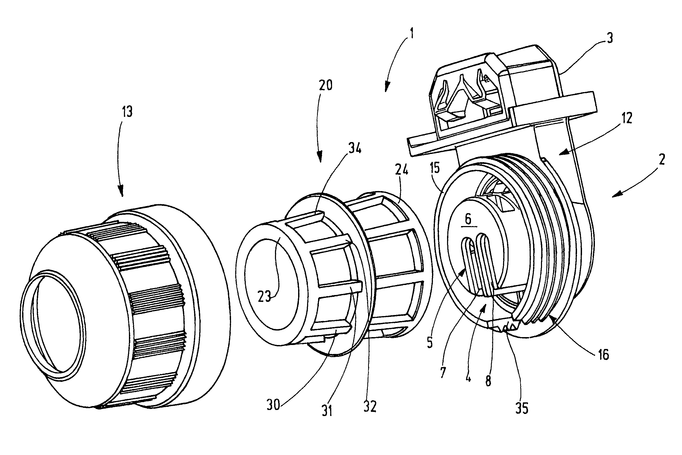
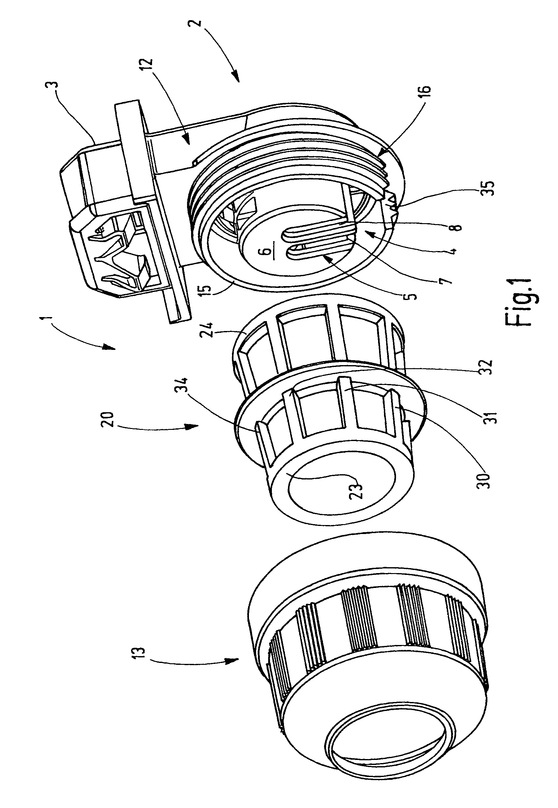
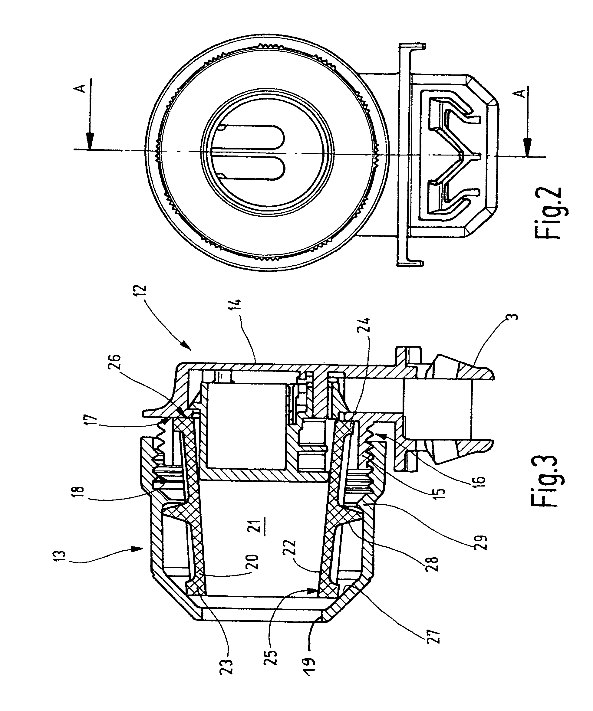
[0023]FIG. 1 shows a lamp socket 1, whose socket housing 2 has a foot 3 for mounting at or on a lamp carrier, and encloses an inner space 4 in which a connecting device 5 illustrated in FIG. 2 is accommodated. The connecting device 5 serves for supporting and contacting terminal prongs of a fluorescent lamp. The connecting device 5 is held in the socket housing 2 with a lateral play. It is resiliently supported to compensate for longitudinal tolerances of the fluorescent lamp. A “radial” play of the fluorescent lamp is thereby prevented.

[0024]The connecting device 5 comprises a partial housing 6 which has two insertion slots 7, 8 for the terminal prongs of the fluorescent lamp. In the end regions of the insertion slots 7, 8 contacts are arranged which serve for supporting the terminal prongs of the fluorescent lamp and for maintaining an electric contact therewith.

[0025]As may be seen in FIG. 1, the socket housing 2 is a multi-part component. The socket housing 2 comprises a first, ...


PUM


Abstract

A novel lamp socket finding application with a type of increased protection, has a housing part (13) in which a one-piece elastomer sealing sleeve (20) is preferably rotatably held. The sealing sleeve (20) is at its lamp-side end preferably slightly radially compressible, while it is stiffer in the axial direction. As a result, it yields inward when axially pressed by the frustoconical inner side of the housing part (13). The one-piece construction of the sealing sleeve (20) from a single material, on the one hand, ensures a simple manufacture and, on the other hand, prevents a faulty mounting caused by slipped seals or the like.

Description

CROSS-REFERENCE TO RELATED APPLICATION[0001]This application claims the priority of German Application 10 2005 056 022.9 filed Nov. 24, 2005.BACKGROUND OF THE INVENTION[0002]The invention relates to a sealed lamp socket for a light means, particularly for fluorescent lamps.[0003]In lamps having an increased degree of protection, dust, moisture or water has to be prevented by suitable means from penetrating into the socket. In particular, the electric connecting device for the lamp contacts has to be protected from moisture and water. This applies independently from the type of the light means. For fluorescent lamps or other bar-like light means to be contacted endwise, generally sockets are used which have a sleeve nut providing a seal at the glass tube of the fluorescent lamp. The sleeve nut is at its inside provided with an appropriate seal.[0004]Such a lamp socket is disclosed, for example, in DE 94 05 817 U1. The socket has a socket housing which comprises a stationary first hou...

Claims


Application Information

Patent Timeline
Patent Type & Authority Patents(United States)
IPC IPC(8): H01R33/02
CPCH01R33/0881H01R33/9658
Inventor THIELE, JURGENMEWS, HANS-PETER
Owner VOSSLOH SCHWABE DEUT GMBH
Why Eureka
Try Eureka