Tank retaining system

a technology of retaining system and tank, which is applied in the direction of snap fasteners, machine supports, furniture parts, etc., can solve the problems of potentially unsafe practice, unfavorable situation, and inability to operate the tightening mechanism, so as to reduce the bending moment

Inactive Publication Date: 2008-03-04
XERXES
View PDF13 Cites 6 Cited by
  • Summary
  • Abstract
  • Description
  • Claims
  • Application Information

AI Technical Summary

Problems solved by technology

This situation is obviously undesirable.
This tightening mechanism could not be operated if located at a position where it was in contact with the tank.
This practice was potentially unsafe because it is possible for excavation sidewalls to collapse unless very expensive shoring was used.
Additionally, if there was water in the hole, tightening was difficult.
While the original Man Out of the Hole system has been a dramatic improvement and has generally proven effective, it is not optimal.
First, the system requires installation personnel to maneuver the hook end of the strap onto the retaining loop on the anchoring system, and to maintain tension on the strap once hooked to avoid having the hook disengage from the anchor retaining loop.
This operation requires patience, and time, especially on the part of inexperienced installation personnel.

Method used


Image

  • Tank retaining system
  • Tank retaining system
  • Tank retaining system

Examples


Embodiment Construction

[0028]The present invention will be discussed with reference to preferred embodiments of tank / anchor retainer systems. Specific details, such as specific materials and dimensions, are set forth in order to provide a thorough understanding of the present invention. The preferred embodiments discussed herein should not be understood to limit the invention.

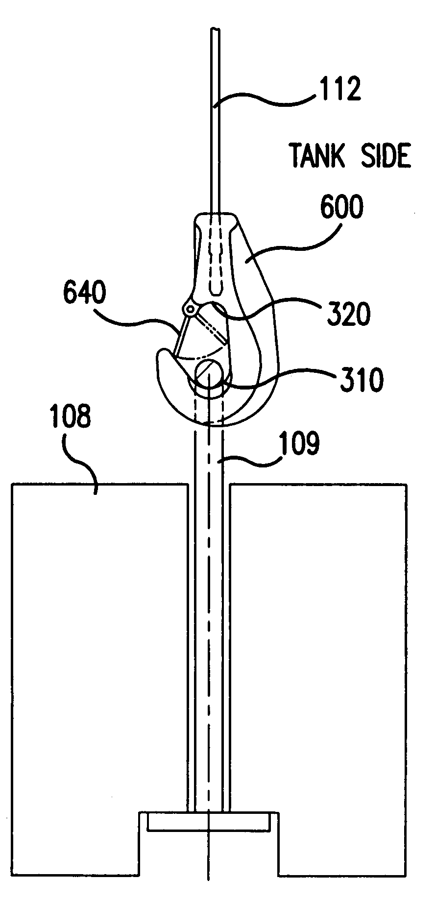
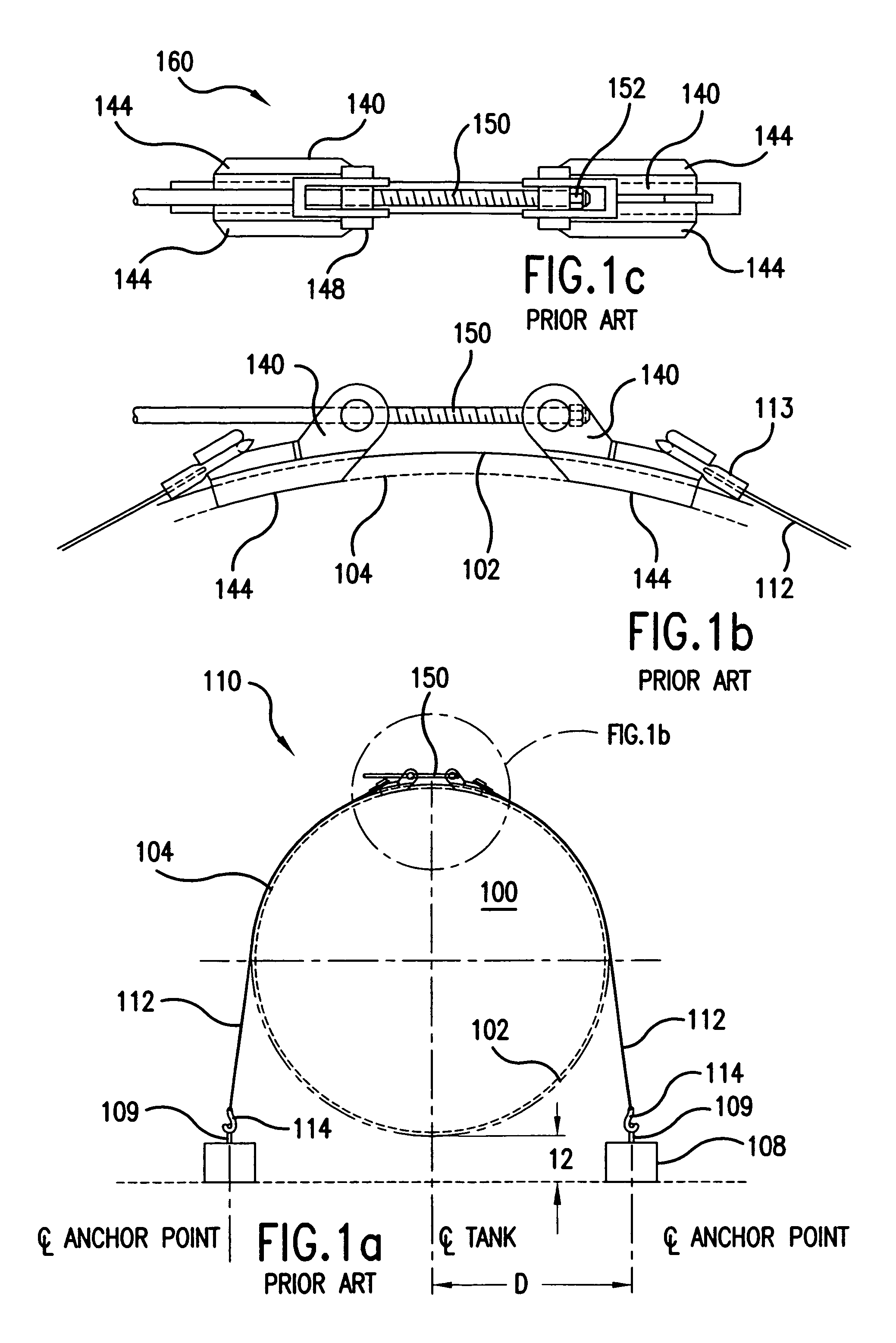
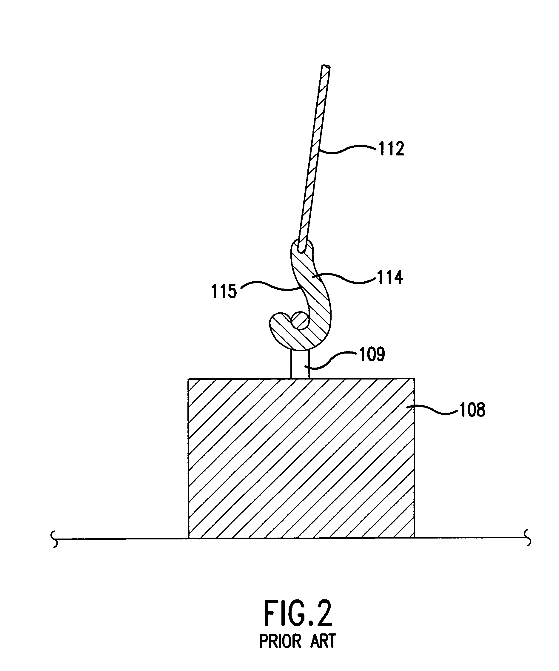
[0029]Referring now to the drawings, wherein like reference numerals designate identical or corresponding parts throughout the several views, a side view of a tank 100 including a prior art Man-Out-Of-The-Hole retainer system 110 is shown in FIG. 1. The tank 100 is ribbed. The top surface of the ribs is indicated in phantom by line 102, while surface of the valleys between the ribs is indicated by line 104. The retainer system 110 includes a pair of fiberglass straps 112 with a hook 114 attached to one end of each of the straps. The hook 114 engages a retaining loop 109 provided on the respective deadman 108.

[0030]FIG. 2 is a cross s...


PUM


Abstract

A retaining system in which straps are provided with hooks that remain engaged with retaining loops even when tension on the straps is released and in which the tightening mechanism includes rods which are located partially below a rib surface on which the straps are placed such that the ends of the rods are near the plane of the strap ends, thereby greatly reducing the bending moment applied to the strap ends and threaded rods. The hook preferably includes a cavity opposite the hook end that will engage the retaining loop when no tension is on the line. In some embodiments, the hook includes a spring-loaded retaining clip to further ensure that the hook does not become disengaged from the retaining loop. The tightening mechanism includes two rods, each of which is positioned to one side of a rib on which the straps rest.

Description

[0001]This application is a continuation of U.S. patent application Ser. No. 10 / 135,367, filed May 1, 2002, now U.S. Pat. No. 7,028,967.BACKGROUND OF THE INVENTION[0002]1. Field of the Invention[0003]The invention relates to storage tanks generally, and more particularly to a retainer system for securing a tank to an anchor such as a deadman or a slab.[0004]2. Discussion of the Background[0005]Underground storage tanks are commonly used for the storage of liquids, including gasoline, other petroleum products, and wastewater. These tanks are generally cylindrical in shape, with either curved (e.g. hemispherical) or flat ends. Underground storage tanks may be made of many materials, including steel and fiber reinforced plastic (referred to herein as FRP and fiberglass). Such tanks may be single or multi-walled.[0006]USTs are installed in a wide variety of locations and under a wide variety of conditions. In some locations, the water table is high enough such that some or all of the US...

Claims


Application Information

Patent Timeline
Patent Type & Authority Patents(United States)
IPC IPC(8): E04B1/00B65D88/76F16G11/00
CPCB65D88/76F16G11/00Y10T24/31F16G11/143
Inventor BURWELL, JOHNMORRISSETTE, DOUGLASBERG, SR., ROBIN L.GRAMS, DAVID
Owner XERXES
Why Eureka
Try Eureka