
Interlock wiring communication system for elevators

a technology for interlocking wiring and communication systems, which is applied in the direction of elevators, instruments, computer control, etc., can solve the problems of more complex and labor-intensive traditional elevator wiring installations, more complex maintenance and fault finding in these traditional wiring approaches, and more complicated wiring installations. , to achieve the effect of reducing the number of wires

Inactive Publication Date: 2008-02-26
THYSSENKRUPP ELEVATOR AG (DE)
View PDF21 Cites 21 Cited by
  • Summary
  • Abstract
  • Description
  • Claims
  • Application Information

AI Technical Summary

Benefits of technology

This approach simplifies wiring installations, reduces labor and costs, provides a secure transmission medium, and offers a flexible transmission system that minimizes complex schemes, while ensuring reliable communication and power supply to elevator components.

Problems solved by technology

Hence, traditional elevator system wiring installations were both more labor intensive and more complex in terms of the higher volume of conductors needed in the wiring schemes.
Maintenance and fault finding in these traditional wiring approaches are also more challenging in comparison to more simplified wiring installations.
However, these systems use serial communications over data busses, and therefore, still require discrete wiring installation, which is relatively labor intensive.
Therefore, equipment using PLC communication are subjected to changes in impedance and power line noise which occur as a result of load changes from different electrical appliances drawing power from various AC sockets within the building.
Furthermore, PLC communications is subjected to restrictions and regulations (in US, by the FCC) that are imposed on modulation frequencies, conducted and radiated emissions, and interfacing safety between the power line and communication equipment accessing the power line transmission medium.
Finally, transmission of signals over the AC wiring of a building does raise a security risk, where signal tampering and hacking is aided through the use of readily available wall sockets.

Method used


Image

  • Interlock wiring communication system for elevators
  • Interlock wiring communication system for elevators
  • Interlock wiring communication system for elevators

Examples


Embodiment Construction

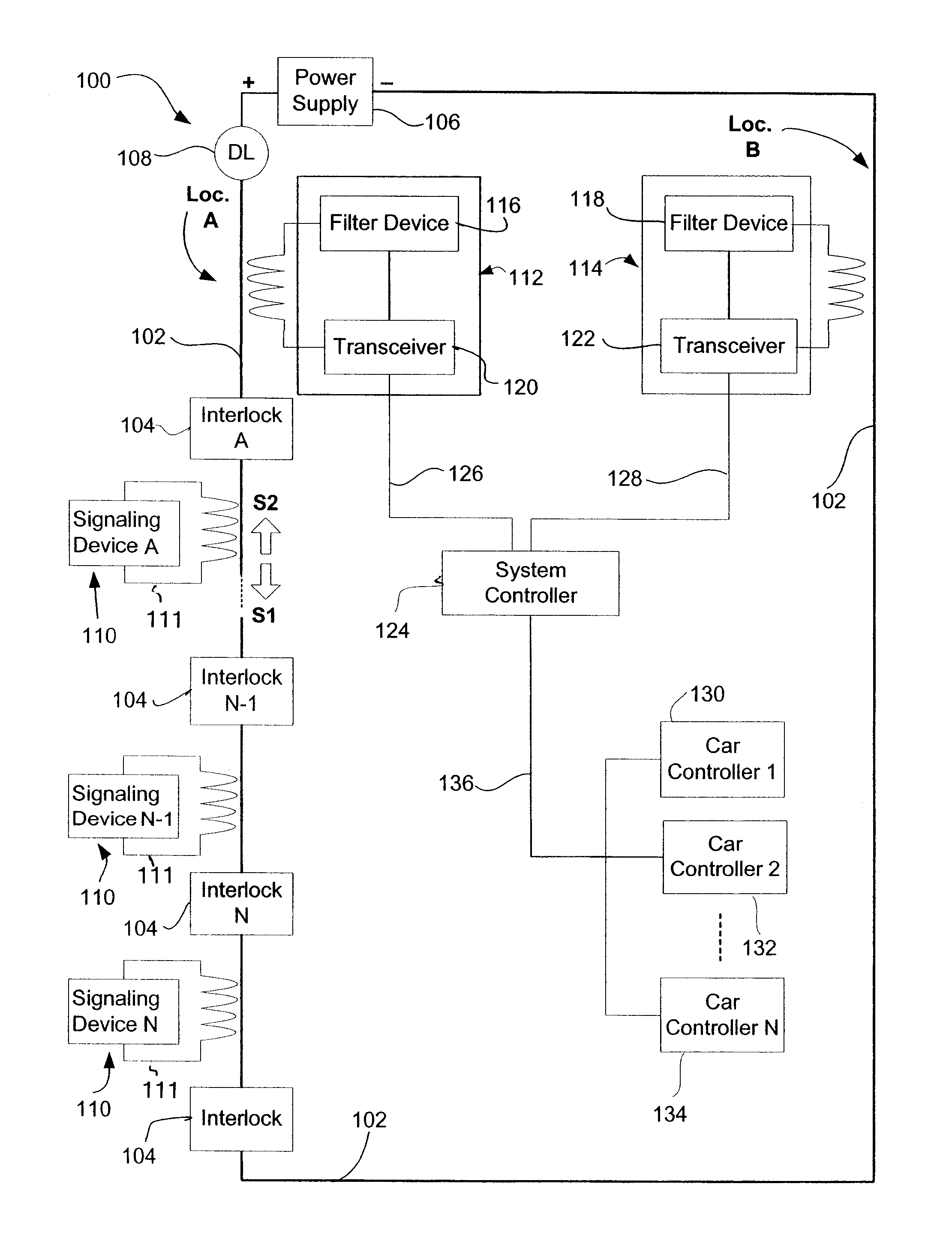
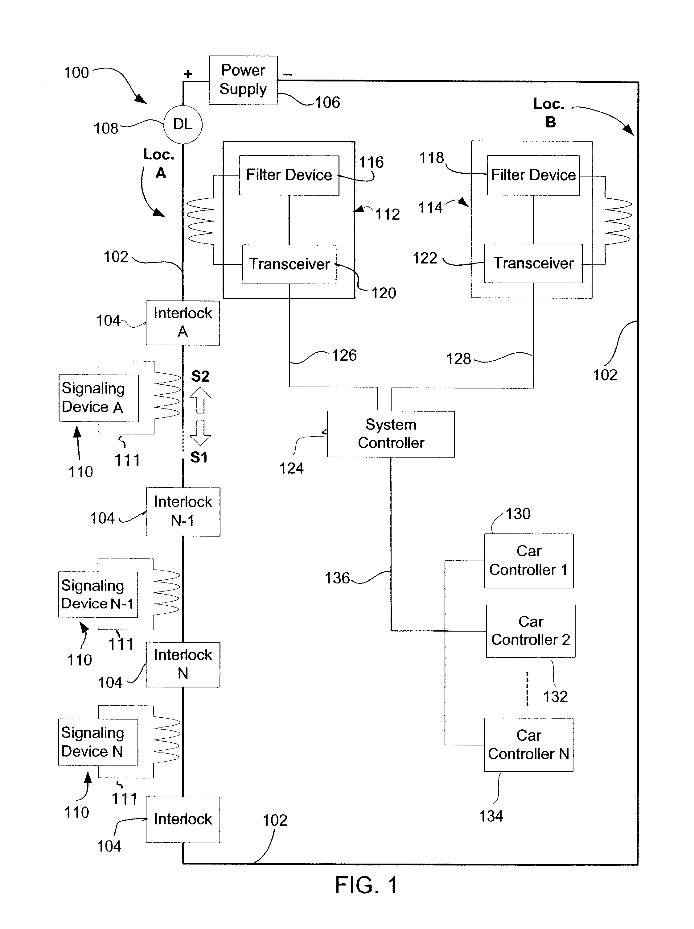
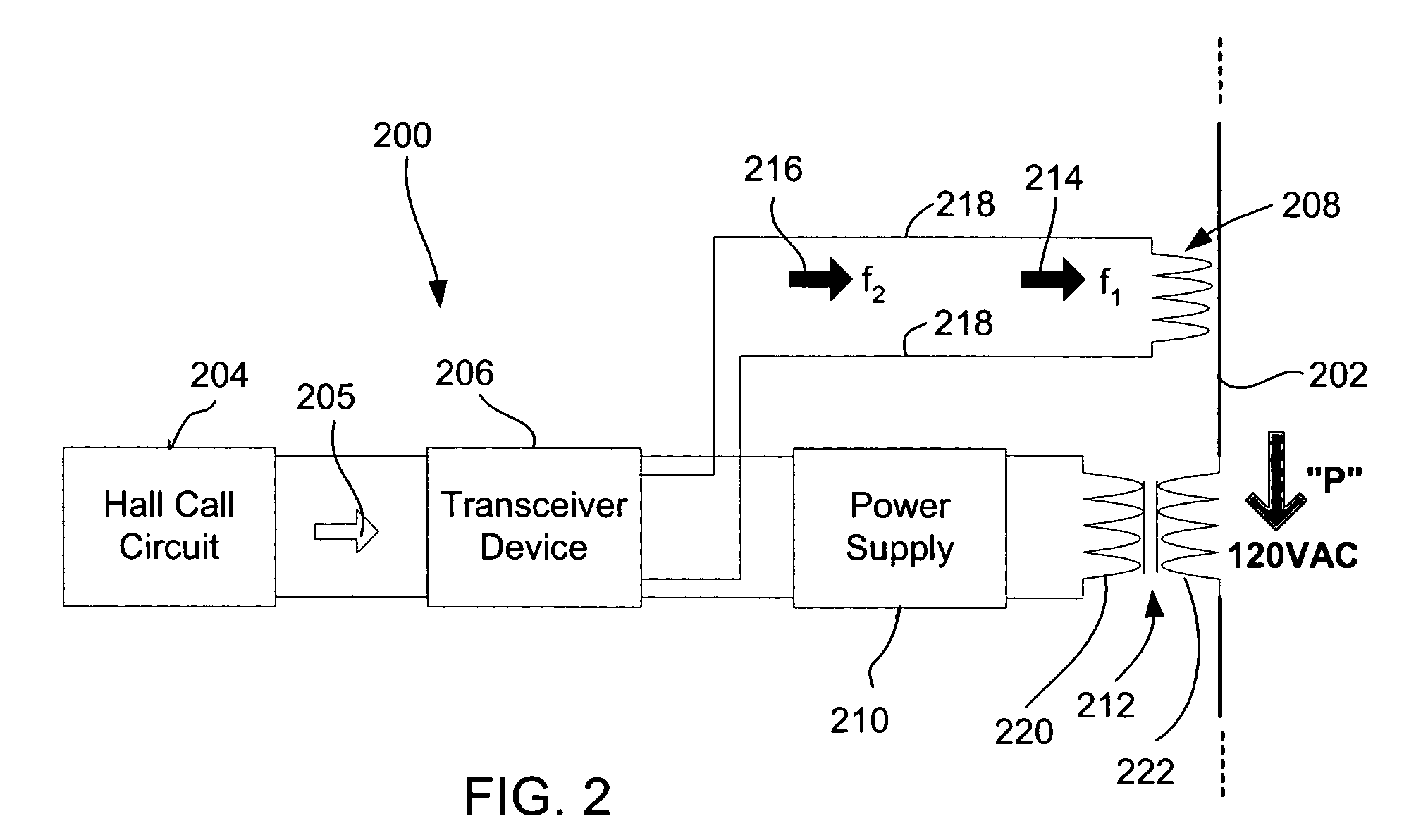
[0021]FIG. 1 shows an embodiment the a door interlock wiring system 100 according to the present invention. The interlock wiring system comprises a plurality of interlock devices 104 connected in series by interlock wiring 102. The interlock wiring 102 carries 120VAC, provided by a power supply 106 through a relay switch 108. The interlock wiring 102 in combination with interlock devices 104 prevents an elevator cab (not shown) from moving when the doors of that elevator are open. If all the interlock devices 104 are closed (i.e., elevator doors are closed), relay switch 108 is activated and the 120VAC electrical signal from power supply 106 flows through the interlock wiring circuit 102. Therefore, the elevator car is able move. Alternatively, if there is a break (i.e., open circuit) in one of the door interlock devices 104 due to an elevator door being in the open position, the relay switch 108 is deactivated, preventing the 120VAC electrical signal from flowing in the interlock w...


PUM


Abstract

The systems and methods of present invention invoke an elevator communication system for providing communication between a plurality of hall fixture devices and at least one elevator system controller. The elevator communication system includes at least one elevator door interlock wiring circuit, which has a first and a second portion. A first transceiver device is coupled to the first portion of the door interlock wiring for transmitting and receiving signals between the at least one elevator system controller and the plurality of hall fixture devices over the interlock wiring. A second transceiver device is coupled to the second portion of the door interlock wiring for transmitting and receiving the signals between the at least one elevator system controller and the plurality of hall fixture devices over the interlock wiring.

Description

FIELD OF INVENTION[0001]The present invention is related to an apparatus and method for providing simplified wiring in elevator systems. More particularly, the present invention is related to using the existing wiring infrastructure within an elevator system for signal communications and control.BACKGROUND OF INVENTION[0002]Traditionally, signaling devices within elevator systems, such as hall call push buttons, hall lanterns, and positions indicators, which required separate wiring. For example, a twenty floor building would require a signal conductor for each UP and DOWN elevator call button for each floor, where nineteen of the twenty floors would have both UP and DOWN call buttons. Therefore, thirty eight signal conductors would be needed for these nineteen floors. The ground floor and top floor (floor twenty) would respectively have an UP and DOWN call button, which would each require a signal conductor. This brings the total number of signal conductors for the hall call button...

Claims


Application Information

Patent Timeline
Patent Type & Authority Patents(United States)
IPC IPC(8): B66B1/28B66B1/00B66B1/34B66B1/46B66B13/22
CPCB66B1/34B66B1/3415B66B1/468B66B13/22
Inventor SMITH, RORYSOEMARDJAN, SAN ARANGGINICKERSON, JAMES A.HUFF, RANDOLPH W.
Owner THYSSENKRUPP ELEVATOR AG (DE)
Learn More