Failure localization in a transmission network
- Summary
- Abstract
- Description
- Claims
- Application Information
AI Technical Summary
Benefits of technology
Problems solved by technology
Method used
Image
Examples
Embodiment Construction
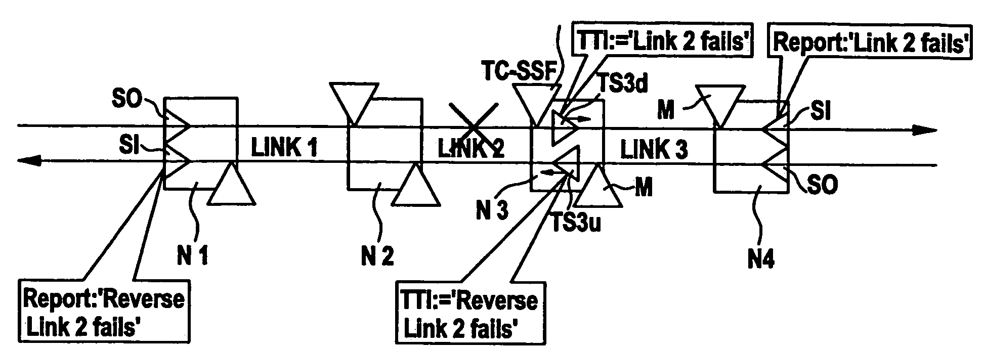
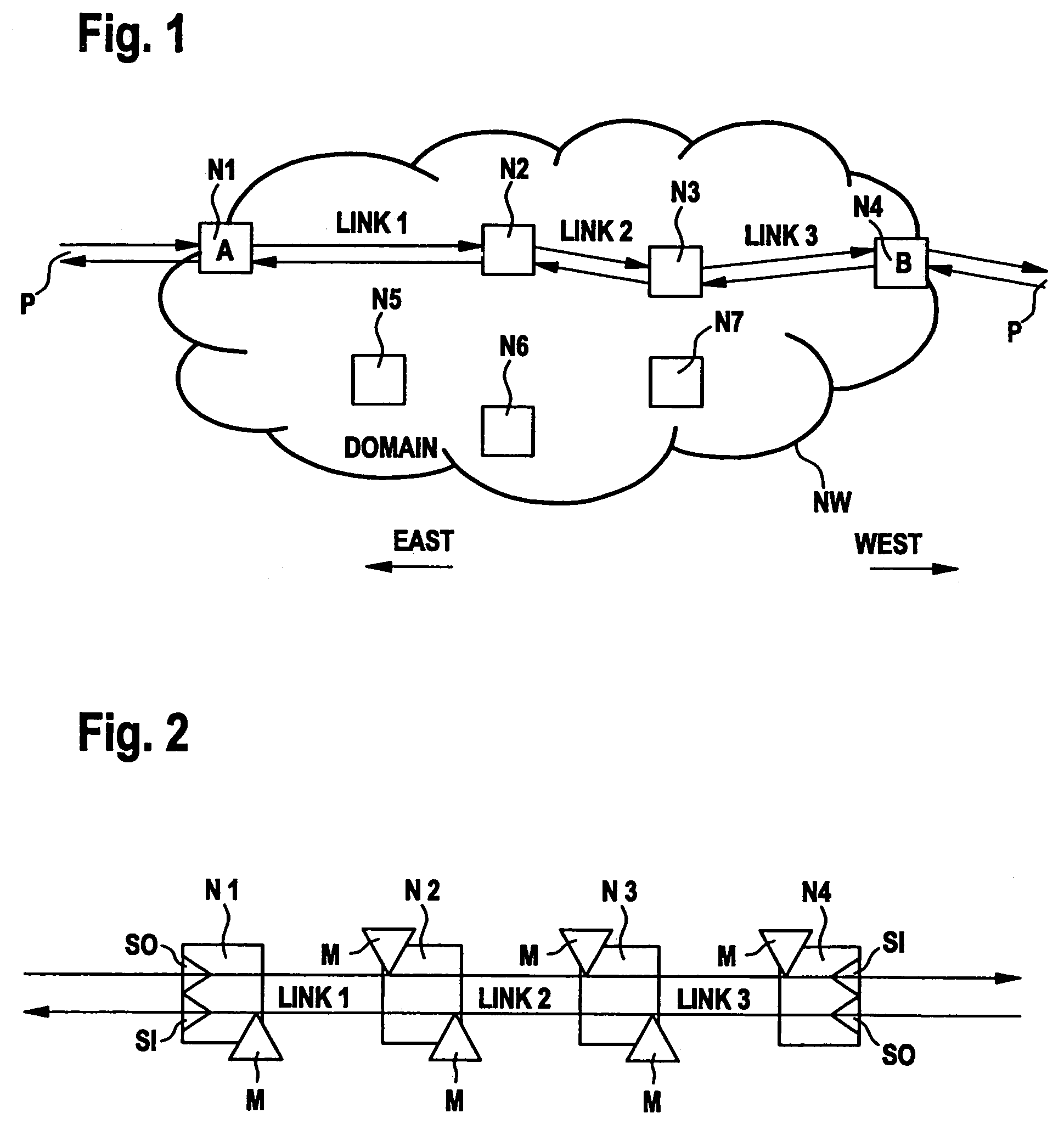
[0024]FIG. 1 shows a transmission network NW containing a number of network elements N1-N7. The network elements are physically interconnected in an arbitrary mesh structure, which is not shown in the example. Only links 1-3 interconnecting network elements N1, N2, N3, and N4, respectively, are shown in the figure. A logical connection (sometimes also referred to a sub-network connection) is established along these links, which carries a bi-directional path signal P. This path is used by way of example to demonstrate fault localization according to the invention.
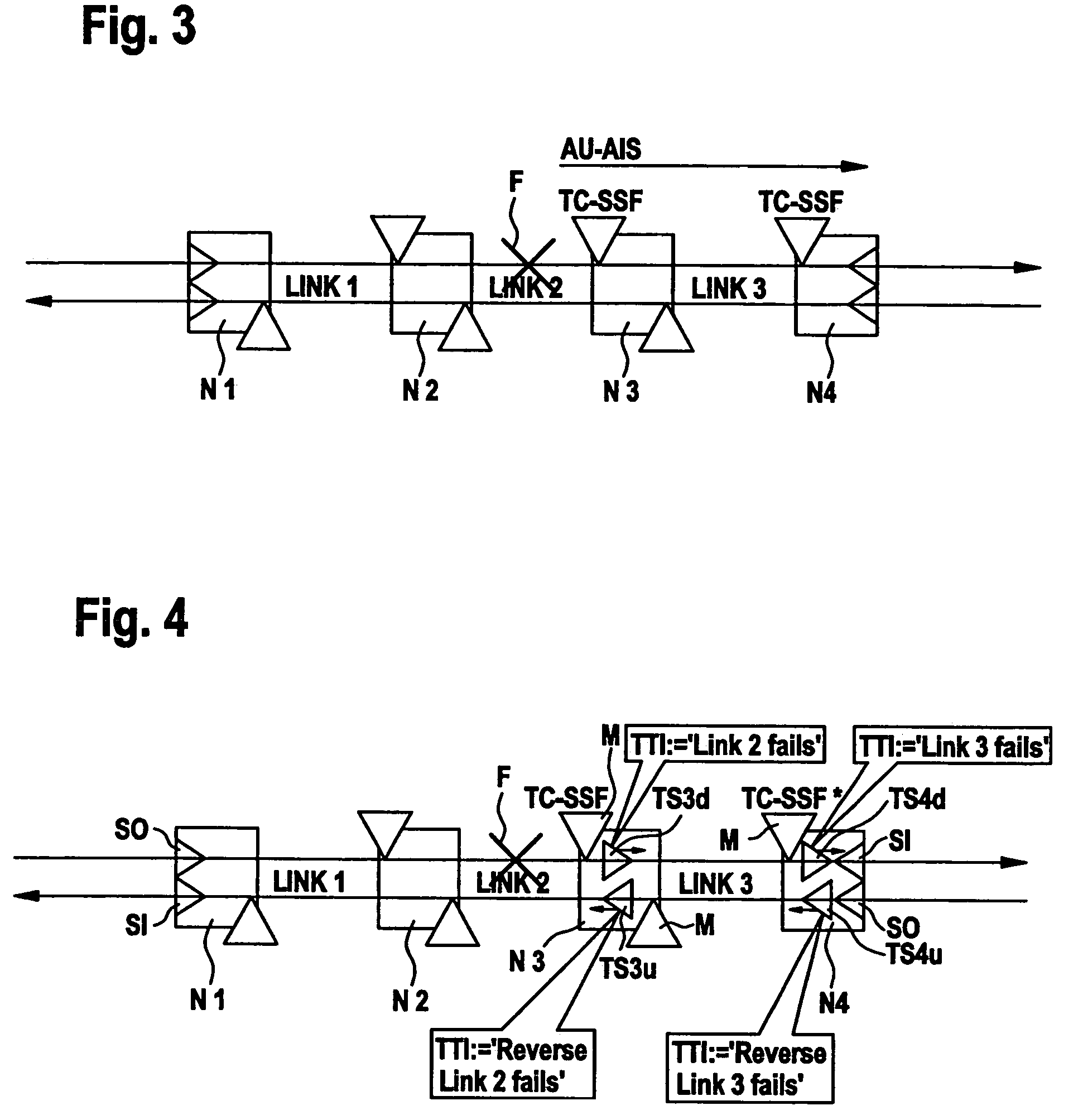
[0025]If the connection from N1 to N4 fails anywhere, subsequent network elements will typically create secondary alarm reports towards the network management plane, which then has to find out the exact location of the primary fault from all these alarms. In order to simplify this fault localization process, use is made of the tandem connection monitoring functions specified in ITU-T recommendations G.707 (SDH), G.709 (OTH),...
PUM
 Abstract
Description
Claims
Application Information
 - R&D
- Intellectual Property
- Life Sciences
- Materials
- Tech Scout
- Unparalleled Data Quality
- Higher Quality Content
- 60% Fewer Hallucinations
Browse by: Latest US Patents, China's latest patents, Technical Efficacy Thesaurus, Application Domain, Technology Topic, Popular Technical Reports.
© 2025 PatSnap. All rights reserved.Legal|Privacy policy|Modern Slavery Act Transparency Statement|Sitemap|About US| Contact US: help@patsnap.com


