Servo writing a disk drive by synchronizing a servo write clock to a reference pattern on the disk and compensating for repeatable phase error

a technology of servo writing and disk drive, which is applied in the direction of maintaining head carrier alignment, digital recording, instruments, etc., can solve the problems of '679 patent not compensating for repeatable phase error, high cost of external servo writers,

Inactive Publication Date: 2008-02-19
WESTERN DIGITAL TECH INC
View PDF75 Cites 153 Cited by
  • Summary
  • Abstract
  • Description
  • Claims
  • Application Information

AI Technical Summary

Benefits of technology

[0017]The present invention may also be regarded as a disk drive comprising a disk comprising a reference pattern having a plurality of sync marks written around the disk, an actuator arm, a head coupled to a distal end of the actuator arm, and a voice coil motor for rotating the actuator arm about a pivot to position the head radially over the disk. The head internal to the disk drive is used to read the reference pattern to generate a read signal. The sync marks are detected from the read signal to generate a sync mark detect signal, and a timing recovery measurement is generated in response to the sync mark detect signal. A frequency control signal is generated in response to the timing recovery measurement, and a servo write clock is generated in response to the frequency control signal. A feed-forward compensation value is generated in response to the timing recovery measurement and the frequency control signal, and the timing recovery measurement is adjusted in response to the feed-forward compensation value to compensate for a repeatable phase error in the timing recovery measurement. The servo write clock and the head internal to the disk drive are used to write the product servo sectors to the disk.

Problems solved by technology

However, external servo writers are expensive and require a clean room environment so that a head positioning pin can be inserted into the head disk assembly (HDA) without contaminating the disk.
Thus, external servo writers have become an expensive bottleneck in the disk drive manufacturing process.
However, the '679 patent does not compensate for the repeatable phase error caused by position errors in the missing bits when the spiral tracks are written to the disk.
The repeatable phase error causes phase incoherency in the product servo sectors of adjacent tracks when servo writing the disk from the spiral tracks.

Method used


Image

  • Servo writing a disk drive by synchronizing a servo write clock to a reference pattern on the disk and compensating for repeatable phase error
  • Servo writing a disk drive by synchronizing a servo write clock to a reference pattern on the disk and compensating for repeatable phase error
  • Servo writing a disk drive by synchronizing a servo write clock to a reference pattern on the disk and compensating for repeatable phase error

Examples


Embodiment Construction

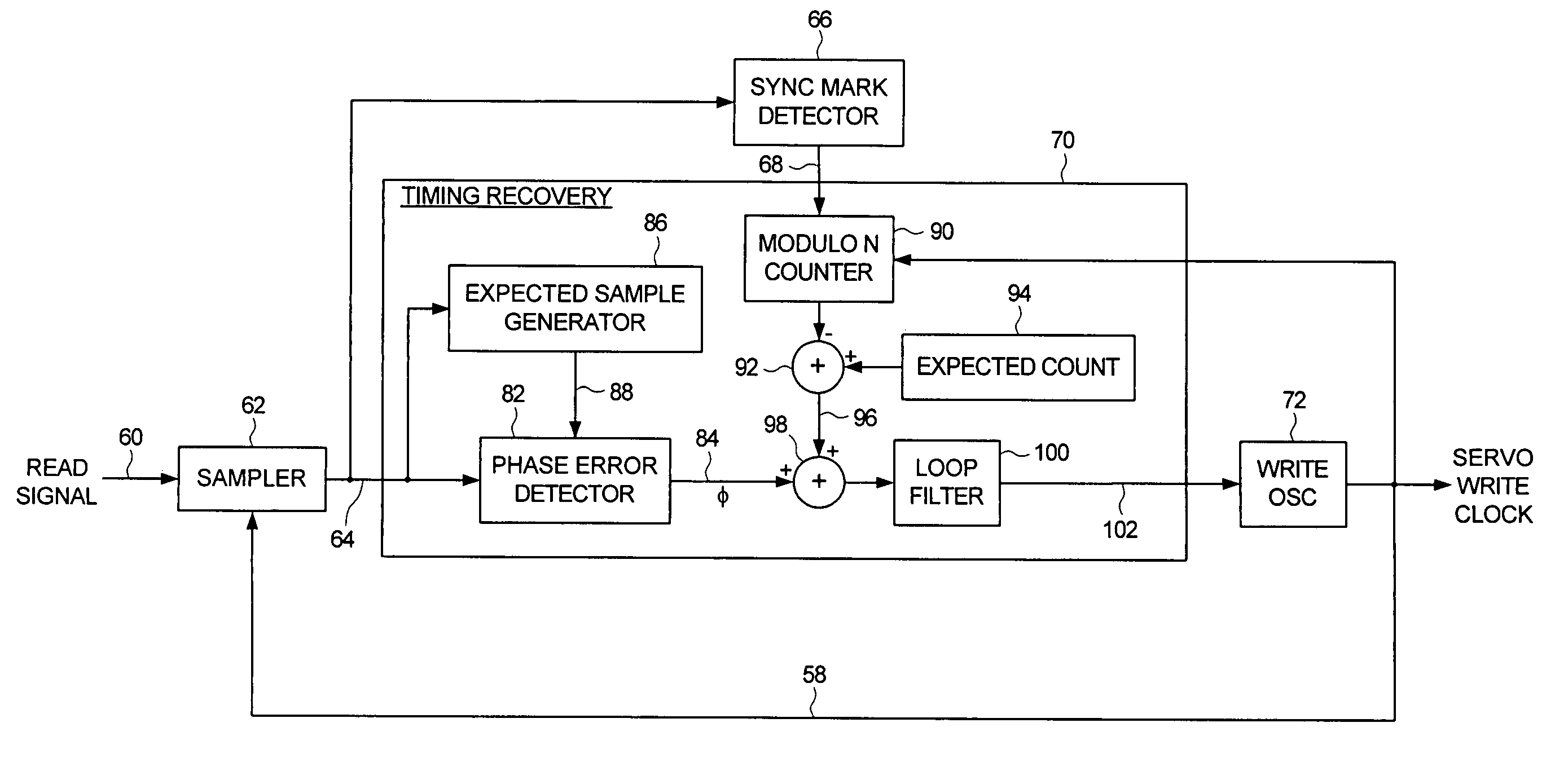
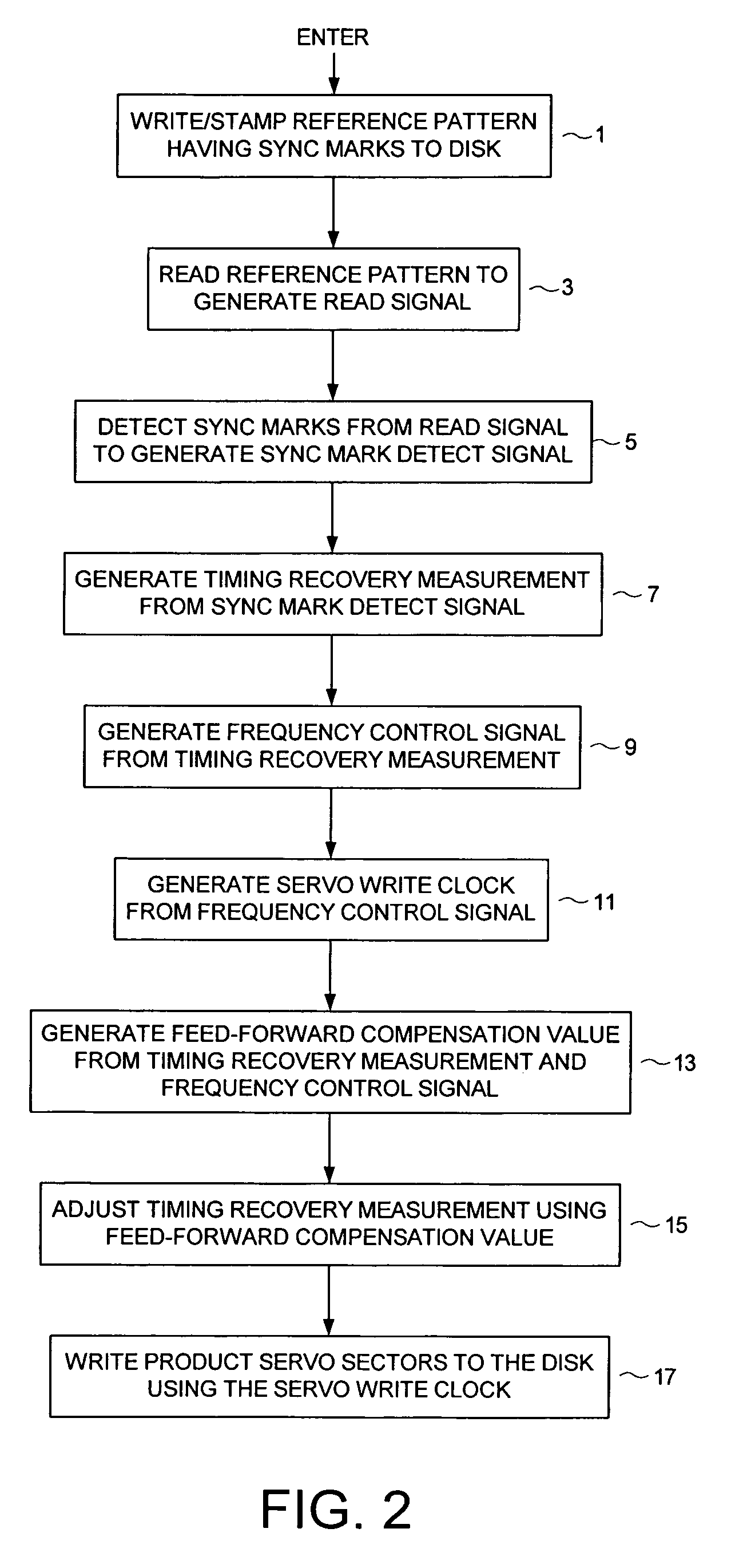
[0038]FIG. 2 shows a method of writing product servo sectors on a disk of a disk drive according to an embodiment of the present invention. The disk drive comprises control circuitry and a head disk assembly (HDA) comprising the disk, an actuator arm, a head coupled to a distal end of the actuator arm, and a voice coil motor for rotating the actuator arm about a pivot to position the head radially over the disk. At step 1, a reference pattern having a plurality of sync marks is written (or stamped) onto the disk. At step 3, the head internal to the disk drive is used to read the reference pattern to generate a read signal. At step 5, the sync marks are detected from the read signal to generate a sync mark detect signal, and at step 7 a timing recovery measurement is generated in response to the sync mark detect signal. At step 9, a frequency control signal is generated in response to the timing recovery measurement, and at step 11 a servo write clock is generated in response to the ...


PUM

PropertyMeasurementUnit
frequencyaaaaaaaaaa
repeatable phase erroraaaaaaaaaa
outer diameteraaaaaaaaaa

Abstract

A method of writing product servo sectors on a disk of a disk drive is disclosed. The disk comprises a reference pattern having a plurality of sync marks written around the disk. The sync marks are detected to generate a sync mark detect signal, and a timing recovery measurement is generated in response to the sync mark detect signal. A frequency control signal is generated in response to the timing recovery measurement, and a servo write clock is generated in response to the frequency control signal. A feed-forward compensation value is generated in response to the timing recovery measurement and the frequency control signal, and the timing recovery measurement is adjusted in response to the feed-forward compensation value to compensate for a repeatable phase error in the timing recovery measurement. The servo write clock and the head internal to the disk drive are used to write the product servo sectors to the disk.

Description

CROSS REFERENCE TO RELATED APPLICATIONS AND PATENTS[0001]This application is related to co-pending U.S. patent application Ser. No. 10 / 769,387 entitled “USING AN EXTERNAL SPIRAL SERVO WRITER TO WRITE REFERENCE SERVO SECTORS AND SPIRAL TRACKS TO A DISK TO FACILITATE WRITING PRODUCT SERVO SECTORS TO THE DISK” filed on Jan. 30, 2004, the disclosure of which is incorporated herein by reference.BACKGROUND OF THE INVENTION[0002]1. Field of the Invention[0003]The present invention relates to disk drives. More particularly, the present invention relates to servo writing a disk drive by synchronizing a servo write clock to a reference pattern on the disk and compensating for repeatable phase error.[0004]2. Description of the Prior Art[0005]When manufacturing a disk drive, product servo sectors 20–2N are written to a disk 4 which define a plurality of radially-spaced, concentric data tracks 6 as shown in the prior art disk format of FIG. 1. Each product servo sector (e.g., servo sector 24) co...

Claims


Application Information

Patent Timeline
Patent Type & Authority Patents(United States)
IPC IPC(8): G11B21/02
CPCG11B5/596G11B5/59666
Inventor LIFCHITS, YAKOV M.YING, WINGCAI, YILINWEERASOORIYA, SIRI S.
Owner WESTERN DIGITAL TECH INC
Why Eureka
Try Eureka