Eureka AIR delivers breakthrough ideas for toughest innovation challenges, trusted by R&D personnel around the world.

Air-fuel ratio controller for internal-combustion engine

a technology of air-fuel ratio controller and internal combustion engine, which is applied in the direction of electrical control, process and machine control, etc., can solve the problems of time-consuming operation, learning value, and inability to purify nitrogen oxides (noxs), and achieve stable emission characteristics and learning value acquisition. stable

Active Publication Date: 2005-04-07
TOYOTA JIDOSHA KK
View PDF1 Cites 31 Cited by
  • Summary
  • Abstract
  • Description
  • Claims
  • Application Information

AI Technical Summary

Benefits of technology

The present invention provides an air-fuel ratio controller for an internal-combustion engine that can maintain stable emission characteristics by allowing stable acquisition of a learning value during sub-feedback control. The controller includes an upstream-side exhaust gas sensor, a downstream-side exhaust gas sensor, main feedback means, and sub-feedback means. The sub-feedback means includes integral-data calculation means, smoothing means, and learning means. The main technical effect of the invention is to improve the accuracy of air-fuel ratio control and achieve stable emission characteristics during engine operation.

Problems solved by technology

The effects of various parameter changes in the internal-combustion engine, however, may cause the actual air-fuel ratio of the exhaust gases with respect to the target air-fuel ratio to tend to be biased to the rich side or the lean side, despite the main feedback control being conducted.
Conversely, the oxygen-occluding state of the catalyst will saturate and nitrogen oxides (NOx) will become unable to be purified (if the actual air-fuel ratio tends to be biased to the lean side).
Accordingly, the conventional controller has had the inconvenience in which the learning value during sub-feedback control significantly fluctuates or in which obtaining a stable learning value becomes a time-consuming operation.
A significant fluctuation in the learning value or a decrease in the learning rate means that biasing of the air-fuel ratio of the exhaust gases toward the lean or rich side is allowed, thus making it impossible to maintain stable emission characteristics.

Method used


Image

  • Air-fuel ratio controller for internal-combustion engine
  • Air-fuel ratio controller for internal-combustion engine
  • Air-fuel ratio controller for internal-combustion engine

Examples


first embodiment

[0024] A first embodiment of the present invention is described below referring to FIGS. 1 to 4.

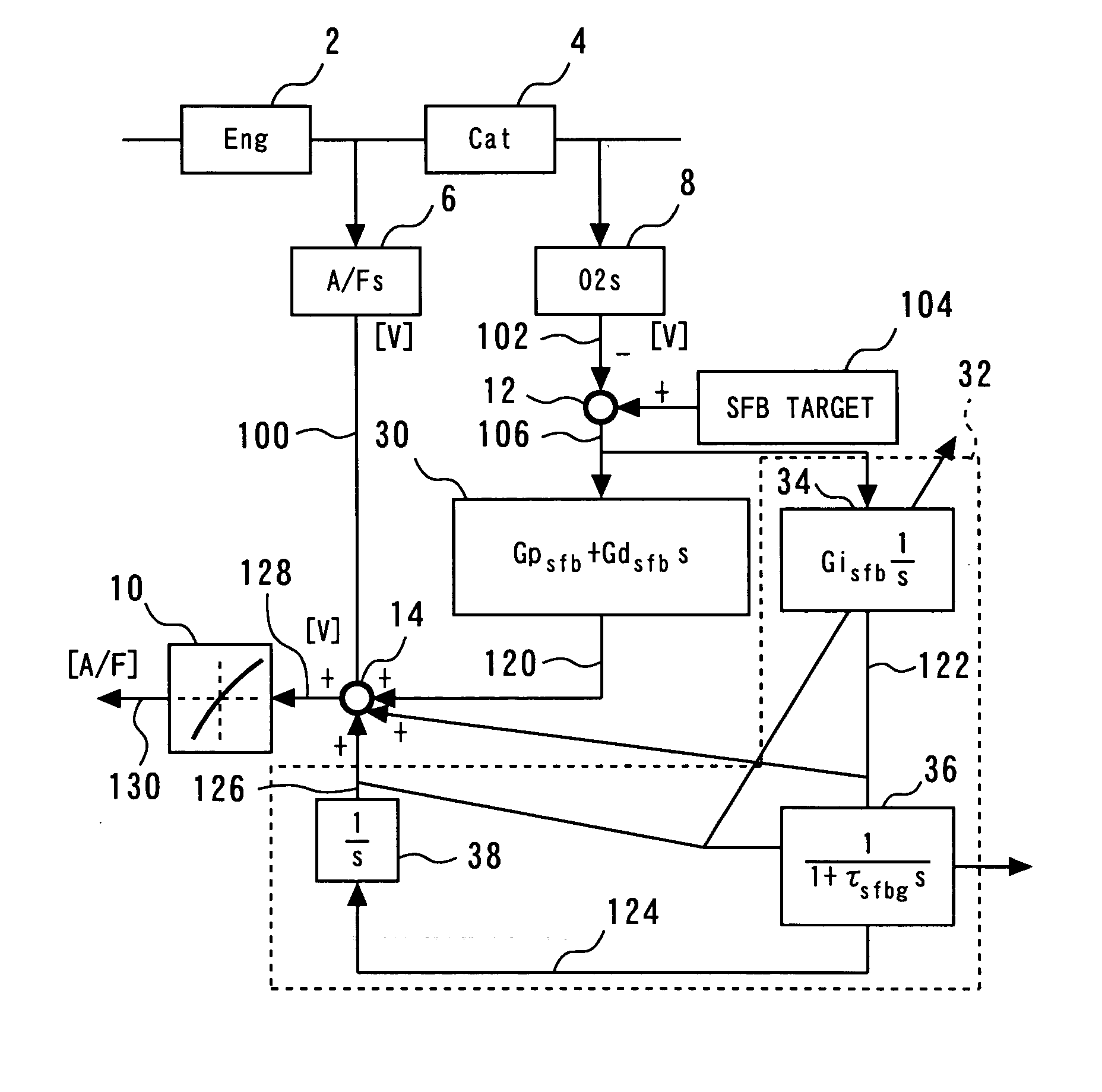
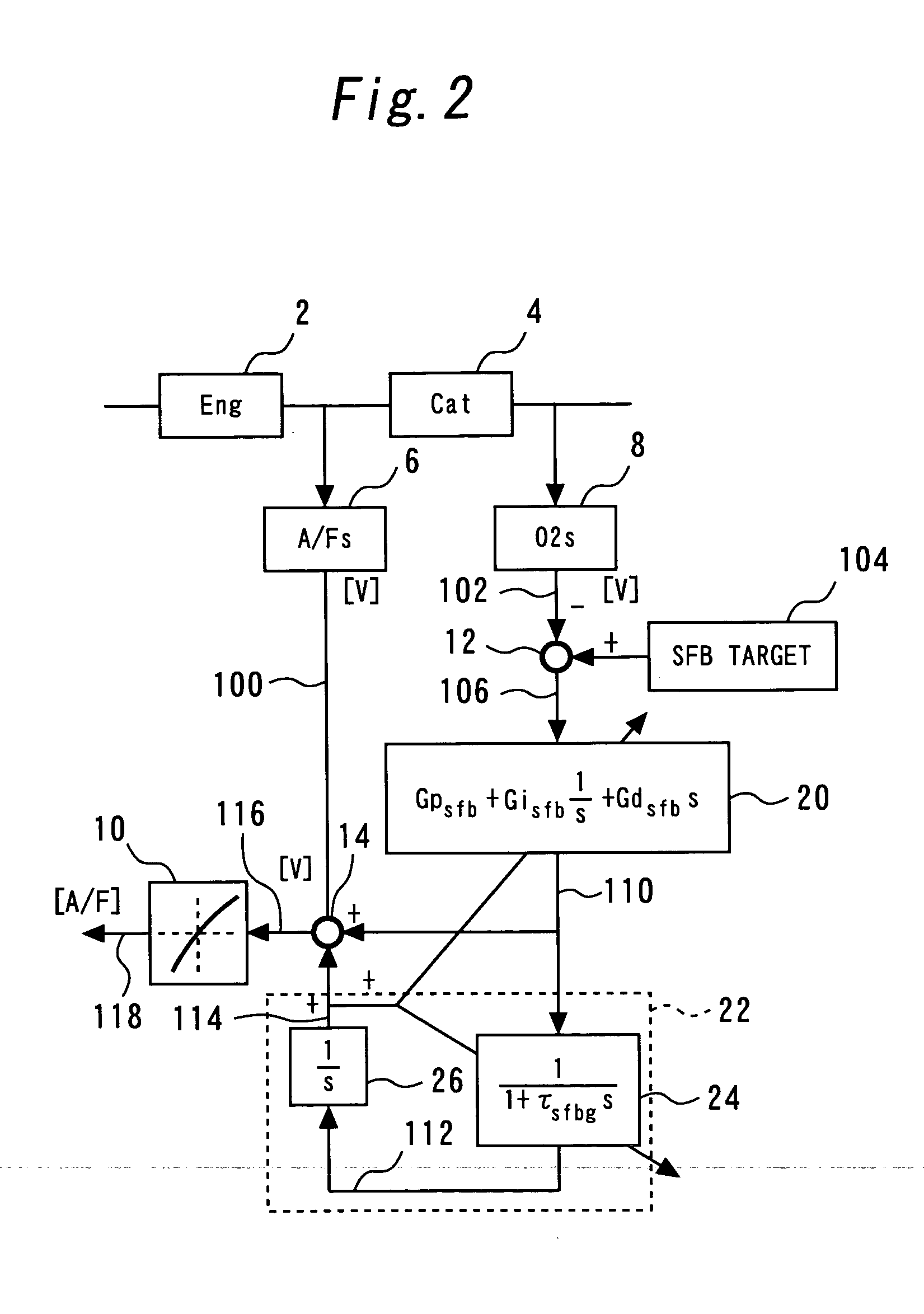
[0025]FIG. 1 is a block diagram showing the configuration of an air-fuel ratio controller according to the first embodiment of the present invention. FIG. 2 is a block diagram showing the configuration of an air-fuel ratio controller which was devised during drafting of the present invention (hereinafter, this air-fuel ratio controller is referred to as the comparison object device). Hereunder, these two air-fuel ratio controllers are contrasted to make features of the air-fuel ratio controller of the present embodiment clear and obvious. Although the air-fuel ratio controller of the present embodiment can conduct main feedback control and sub-feedback control, only sections related to the sub-feedback control are extracted and shown below. A method of conducting the main feedback control is not detailed below since the method does not form a major part of the present invention. The same...

second embodiment

[0060] A second embodiment of the present invention is described below referring to FIG. 5.

[0061] Multiple parameters are used to calculate a learning value in sub-feedback control of an air-fuel ratio controller. In the air-fuel ratio controller of the present invention, as described for the first embodiment, multiple parameters, “sfbi”, “sumdoxs”, and “sfbism”, are also used to calculate a learning value. In conventional devices, values of these parameters concerned with the calculation of a learning value are constantly updated as long as sub-feedback control is being executed under established sub-feedback control execution conditions. If the sub-feedback control execution conditions are not established, however, the above values are cleared and are newly calculated from the beginning when the sub-feedback control execution conditions are established next time. However, the fact that the parameters are cleared each time the sub-feedback control execution conditions fail to be e...

third embodiment

[0066] A third embodiment of the present invention is described below referring to FIG. 6.

[0067] In internal-combustion engines, the fuel cutoff for temporarily stopping fuel injection is conducted if the vehicle speed exceeds a maximum speed limit, if the engine speed reaches a speed limit, or under other required operating conditions. When the fuel cutoff is executed, since unburnt fresh air directly flows into a catalyst 4, an oxygen-occluding state of the catalyst 4 saturates in due course of time and an O2 sensor continues to generate a lean-state output signal for a while after the fuel cutoff. If learning of the learning value in sub-feedback control is conducted under these conditions, the learning value is mis-learnt so that an air-fuel ratio signal 100 from an A / F sensor 6 is corrected to indicate a lean state.

[0068] The air-fuel ratio controller according to the present embodiment, therefore, prevents mis-learning of the learning value during fuel cutoff, by making the ...


PUM


Abstract

An output signal from a downstream-side exhaust gas sensor is fed back into a fuel injection rate so that the air-fuel ratio of the exhaust gases flowing out from a catalyst may match a reference value. In this sub-feedback control process, the integral value of the deviation between the output signal of the downstream-side exhaust gas sensor and a reference value is calculated, and the resulting integral-data signal is smoothed. A learning value for compensating for the permanent error included in an air-fuel ratio signal from an A / F sensor is learnt from the integral-data signal generated by the above smoothing operation.

Description

BACKGROUND OF THE INVENTION [0001] 1. Field of the Invention [0002] The present invention relates to air-fuel ratio controllers for internal-combustion engines, and more particularly to an air-fuel ratio controller for an internal-combustion engine that has respective exhaust gas sensors disposed on both the upstream and downstream sides of a catalyst and controls the supply rate of a fuel in accordance with the output signals sent from the exhaust gas sensors. [0003] 2. Background Art [0004] The apparatuses have heretofore been known which have a wide-area air-fuel ratio sensor (A / F sensor) disposed on the upstream side of a catalyst in an exhaust gas passageway and a dioxide gas sensor (O2 sensor) on the downstream side of the catalyst, and thus which control the air-fuel ratio in accordance with the output signals sent from the two exhaust gas sensors. The A / F sensor is an exhaust gas sensor exhibiting linear output characteristics with respect to an air-fuel ratio. The O2 sensor...

Claims


Application Information

Patent Timeline
Patent Type & Authority Applications(United States)
IPC IPC(8): F02D45/00F02D41/12F02D41/14
CPCF02D41/123F02D41/1402F02D41/1441F02D41/1454F02D41/1456F02D2041/1432F02D41/2454F02D41/2474F02D41/2477F02D2041/1409F02D41/2448
Inventor KATO, NAOTO
Owner TOYOTA JIDOSHA KK
Why Eureka
Eureka Blog
Learn More