Laparoscopic surgical instrument and method

a technology for laparoscopic surgery and instruments, applied in the field of medical instruments and procedures, can solve the problems of cracking and breaking of rubber seals and valves, affecting the operation, and affecting the operation

Inactive Publication Date: 2008-02-19
PENN STATE RES FOUND
View PDF15 Cites 15 Cited by
  • Summary
  • Abstract
  • Description
  • Claims
  • Application Information

AI Technical Summary

Benefits of technology

[0011]A method is provided for gaining access to an anatomical cavity comprising the steps of providing a surgical instrument formed according to any one of the foregoing embodiments of the invention. Manipulating the handles of the instrument so as to close the jaws, and then pressing the jaws against the tissue of the wall of the anatomical cavity so as...

Problems solved by technology

If pressure is lost, the working space collapses, nothing can be seen, via a video system, and the operation comes to a halt.
Known reusable ports are also somewhat difficult to maintain.
Rubber seals and valves crack and break with repeated use and sterilization.
Maintaining and replacing small seals and parts requiring disassembly of the port is tedious and often results in lost or damaged parts.
Also, the trocar portion of the apparatus often becomes dull after several uses.
Using a port that is not sharp, or that leaks is frustrating for the surgeon and potentially dangerous to the patient.

Method used


Image

  • Laparoscopic surgical instrument and method
  • Laparoscopic surgical instrument and method
  • Laparoscopic surgical instrument and method

Examples


Embodiment Construction

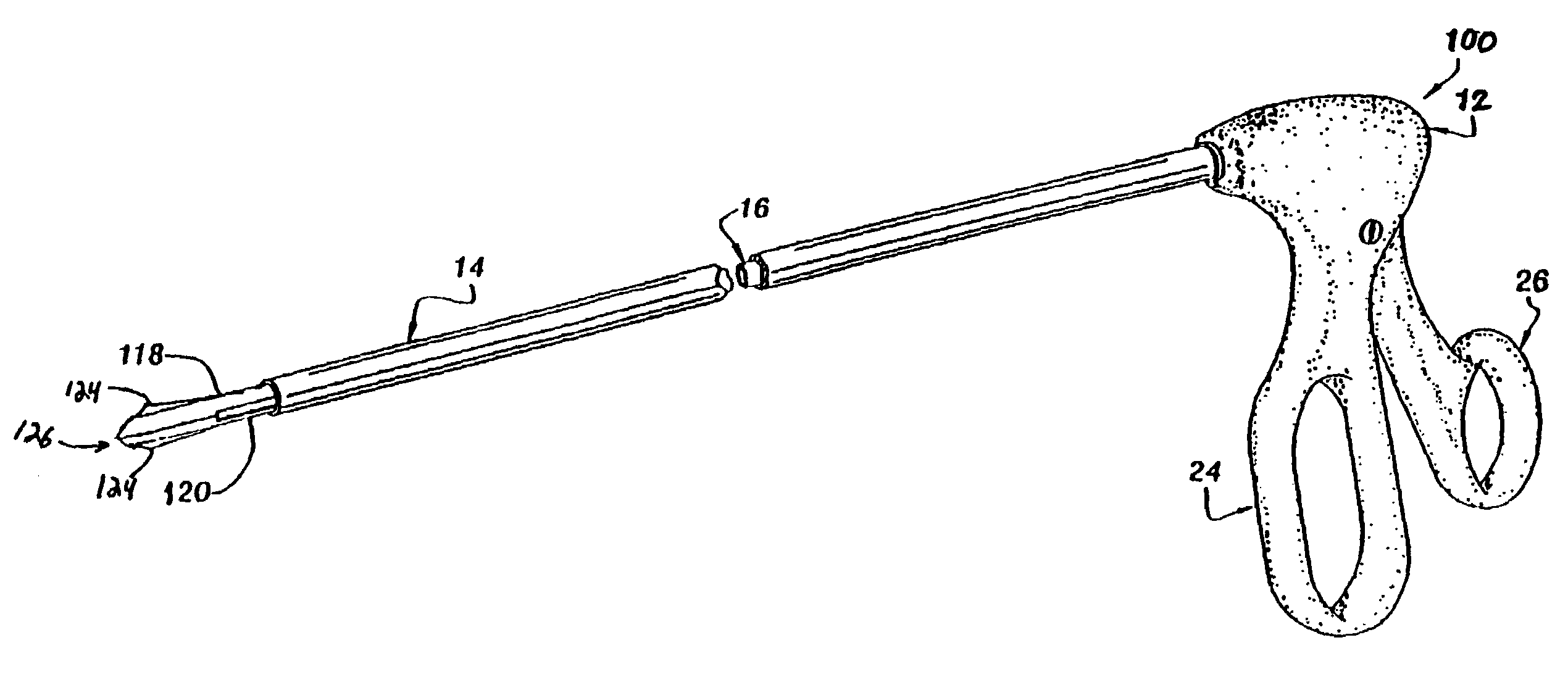
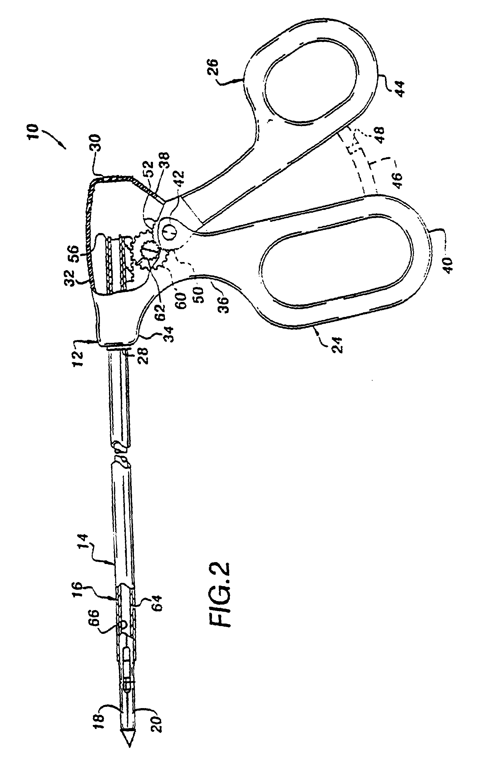
[0020]The following description of the preferred embodiments of the invention are intended to be read in connection with the foregoing drawings and are to be considered a portion of the entire written description of this invention. As used in the following description, terms such as, “horizonal”, “vertical”, “left”, “right”, “up”, and “down”, as well as adjectival and adverbial derivatives thereof (e.g., “horizontally”, “rightwardly”, “upwardly”, etc.) simply refer to the orientation of the structure of the invention as it is illustrated in the particular drawing figure when that figure faces the reader. Similarly, the terms “inwardly” and “outwardly” generally refer to the orientation of a surface relative to its axis of elongation, or axis of rotation, as appropriate. Also, the terms such as “connected” and “interconnected,” when used in this disclosure to describe the relationship between two or more structures, means that such structures are secured or attached to each other eit...


PUM


Abstract

A surgical instrument is provided for use in performing endoscopic procedures having a handle and an elongate tubular member having a proximal end coupled with the handle for being disposed externally of the anatomical cavity and a distal end for being disposed within the anatomical cavity. The distal end further includes a pair of opposed, relatively movable jaws that form a grasping portion operable by manipulation of the handle to releasably grasp a releasable trocar. The releasable trocar has a complementarily shaped shank, a relatively sharp tip and may include a pair of blunt-edge tissue separators that project outwardly from the outer surface of the trocar. In an alternative embodiment, the relatively movable jaws define (i) a grasping portion operable by manipulation of the handle to grasp or cut objects; and (ii) a pair of blunt-edge tissue separators that project outwardly from the outer surface of the jaws so that when the jaws are in a closed position they may be used as a trocar. In another embodiment, a portal tube is sealingly positioned on the elongate tubular member and is operative to move between (i) a first position in which the portal is in a proximal location on the elongate tubular member and in spaced relation to the anatomical cavity, and (ii) a second position in which the portal is in a distal location on the elongate tubular member and in sealed communication with said anatomical cavity. The optional portal may be used with either the releasable trocar or the jaw trocar. A method for using the surgical instrument is also provided.

Description

FIELD OF THE INVENTION[0001]The present invention relates generally to medical instruments and procedures and more particularly, to an instrument for use in laparoscopic or endoscopic surgical procedures.BACKGROUND OF THE INVENTION[0002]Endoscopic and minimally invasive medical procedures, such as laparoscopy, have become widely accepted for surgery and illness diagnosis. This is due to reduced trauma to the patient and reduced hospitalization time. Other techniques exist for creating a working space within the abdominal cavity, but the vast majority of laparoscopic operations worldwide are performed using the technique of pneumoperitoneum.[0003]At the beginning of all laparoscopic cases, a small incision is made, followed by a small (1 cm) hole in the remaining layers of the abdominal wall so as to gain access to the peritoneal cavity. An alternative method of gaining access to the peritoneal cavity is to insert a small needle through the abdominal wall and to instill CO2 through t...

Claims


Application Information

Patent Timeline
IPC IPC(8): A61B17/28A61B17/00A61B17/34
CPCA61B17/29A61B17/295A61B17/3417A61B17/3421A61B2017/00473A61B2017/2923A61B2017/2926A61B2017/3456A61B2017/346
Inventor HALUCK, RANDY S.
Owner PENN STATE RES FOUND
Why Eureka
Try Eureka