
Apparatus and method for multi-channel equalization

a multi-channel equalization and apparatus technology, applied in the field of apparatus and method for multi-channel equalization, can solve the problems of reducing channel matching, reducing channel equalization, and reducing channel equalization, so as to improve channel equalization, reduce system resources, and select the reference channel sufficiently fast

Inactive Publication Date: 2008-02-12
UNITED STATES OF AMERICA THE AS REPRESENTED BY THE SEC OF THE ARMY
View PDF4 Cites 21 Cited by
  • Summary
  • Abstract
  • Description
  • Claims
  • Application Information

AI Technical Summary

Benefits of technology

"The patent describes an improved way to match the frequency response of each channel in a multi-channel communication system to a chosen reference channel. This is done by using a tapped delay line filter in each channel and adapting the others to match the reference in both phase and amplitude. The process is performed during system calibration cycles and results in optimal or near-optimal channel matching. The invention aims to select the reference channel quickly and efficiently, without draining system resources."

Problems solved by technology

However, the amount of attenuation is limited by the level of matching between the channels.
The reference channel could then fail or degrade over time and greatly reduce the channel matching.

Method used


Image

  • Apparatus and method for multi-channel equalization
  • Apparatus and method for multi-channel equalization
  • Apparatus and method for multi-channel equalization

Examples


Embodiment Construction

[0011]Referring now to the drawings wherein like numbers represent like parts

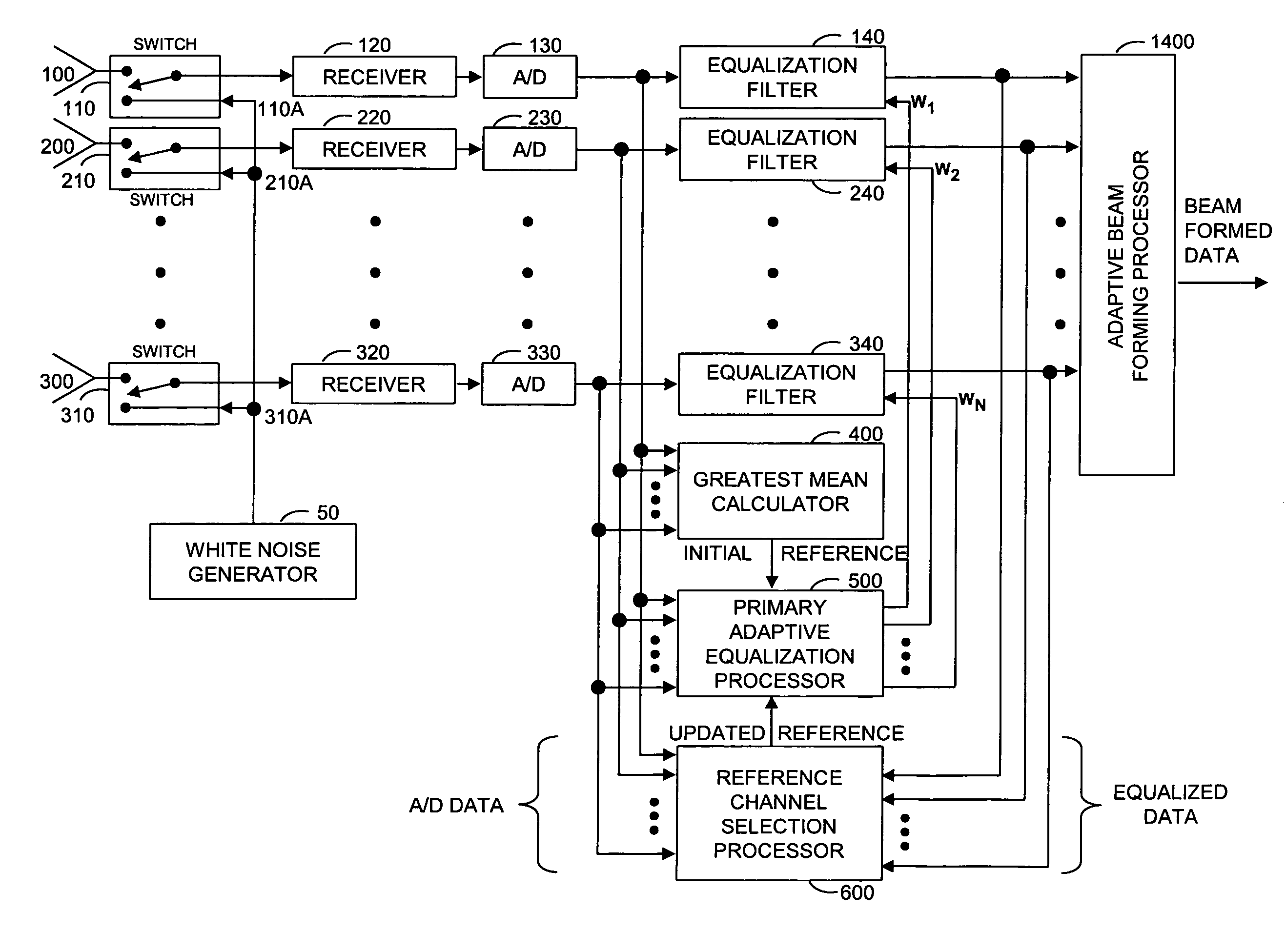
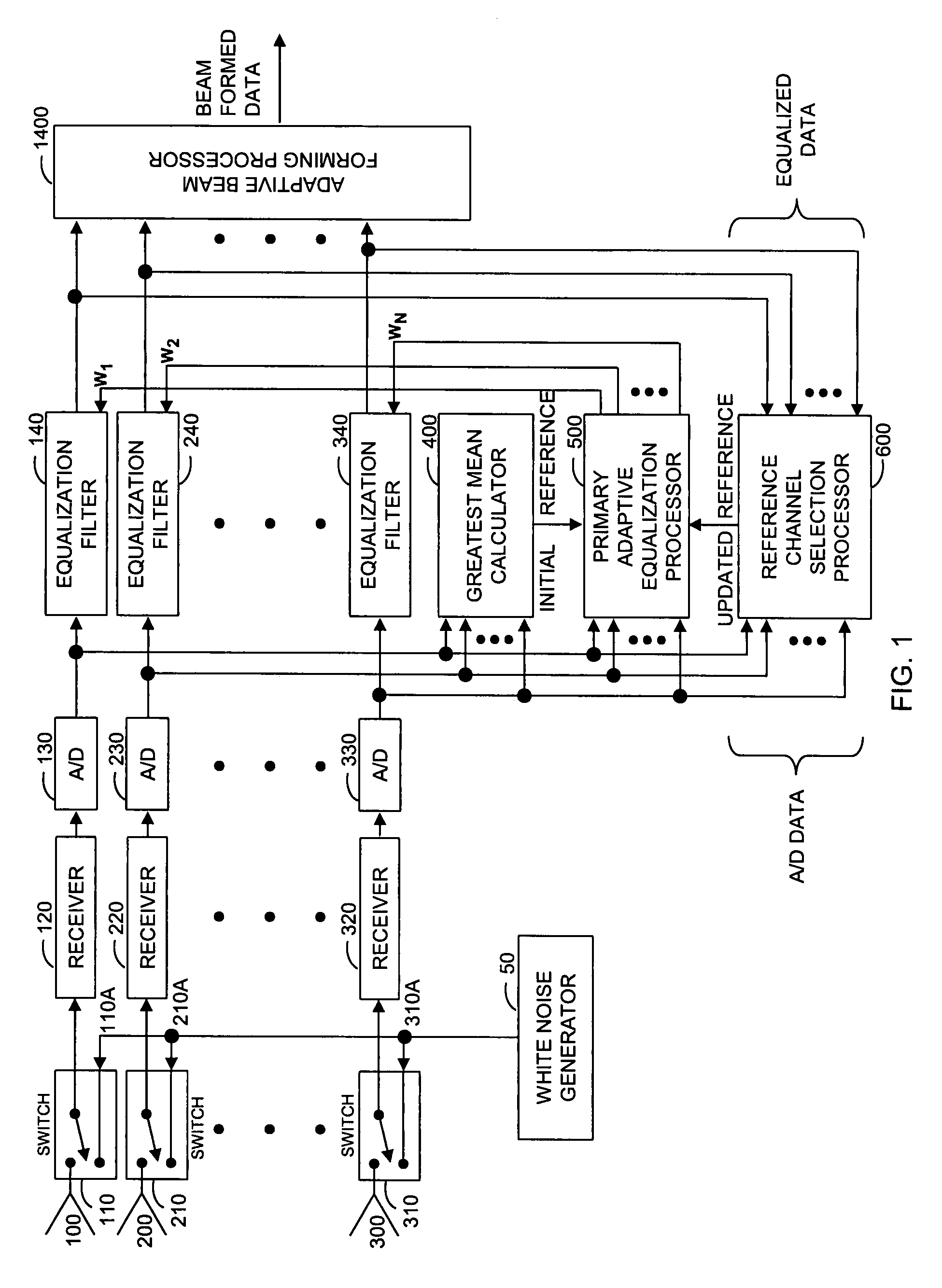
[0012]FIG. 1 shows a multi-channel communication system that performs equalization using adaptive processing techniques. During system operation, signals are received through inputs 100, 200, and 300, which correspond to receiver 120, receiver 220, and receiver 320. During system calibration, a white noise generator 50 is switched so that input 110A goes to receiver 120, input 210A goes to receiver 220, and input 310A goes to receiver 320. Any number of channels may be employed as is appropriate for a given application.

[0013]The first receiver channel includes a switch controlling inputs 100 and 110A which in turn are coupled to receiver 120. The output of receiver 120 is the input of analog-to-digital (A / D) converter 130 for sampling the signal received by receiver 120 and providing resultant samples to primary equalization filter 140, to the greatest mean calculator 400, to the primary adaptive equalizati...


PUM


Abstract

A communication system with a multi-channel array antenna utilizes a receiver matching process that adapts the pass band frequency response of each channel to a selected reference channel. This process is implemented digitally by inserting a tapped delay line filter in each channel, selecting one of the channels as a reference, and adapting the others to match the reference in both phase and amplitude. The process is performed for each system calibration cycle, which occurs just before receive data is captured and processed. The improvements include an apparatus and an algorithm that select a reference channel in the adaptive process during each system calibration cycle, producing optimal, or near optimal, channel matching.

Description

DEDICATORY CLAUSE[0001]The invention described herein may be manufactured, used and licensed by or for the Government of the United States of America for governmental purposes without the payment to the inventors of any royalties thereon.BACKGROUND OF THE INVENTION[0002]Multi-channel array antennas in various systems have been used to digitally form antenna beams for the past few decades. By digitally forming the antenna beam, adaptive processing techniques can be implemented to shape beam patterns so that energy received in the direction of interference is minimized while energy received in the direction of the desired signal is maximized. This process is typically referred to as adaptive beam forming. Some examples of applications implementing adaptive beam forming techniques include radar, sonar, seismic, imaging, cellular, satellite, and global positioning systems.[0003]Adaptive beam forming processes attenuate interference signals impinging on the antenna array by placing beam ...

Claims


Application Information

Patent Timeline
Patent Type & Authority Patents(United States)
IPC IPC(8): H03H7/40H03K5/159H04B7/08H04L25/03
CPCH04B7/088H04L25/03133H04L2025/03375H04L2025/03477H04L2025/0377
Inventor LEVASSEUR, JEFFREY K.WORLEY, BRENT A.
Owner UNITED STATES OF AMERICA THE AS REPRESENTED BY THE SEC OF THE ARMY
Learn More