Circuit and method for driving a capacitive load, and display device provided with a circuit for driving a capacitive load

a capacitive load and display device technology, applied in the direction of static indicating devices, pulse techniques, instruments, etc., can solve the problems of large power consumption of video signal line driving circuits and inability to achieve further reduction of power consumption, and achieve the effect of reducing power consumption

Inactive Publication Date: 2008-02-12
SHARP KK
View PDF10 Cites 6 Cited by
  • Summary
  • Abstract
  • Description
  • Claims
  • Application Information

AI Technical Summary

Benefits of technology

[0014]It is thus an object of the present invention to provide a driving circuit and a driving method for driving a capacitive load by applying to the capacitive load a voltage whose polarity is periodically inverted, as in a liquid crystal display device, wherein the driving circuit and the driving method can decrease the power consumption more than in conventional methods.
[0020]With this configuration, after the capacitive load has been charged by the output circuit, the capacitor becomes charged with the same potential and the same polarity as the capacitive load by connecting the capacitor in parallel to the capacitive load in a first predetermined period within the OFF period during which the output circuit is electrically disconnected from the capacitive load, and the capacitive load becomes charged to the same potential as the capacitor but at opposite polarity as in the first predetermined period by connecting the capacitor in parallel to the capacitive load but with opposite orientation in a second predetermined period within the OFF period. Thus, in the second predetermined period of the OFF period, the capacitive load is precharged by the accumulated charge of the capacitor, so that the potential change of the capacitive load to be changed by the output circuit after the OFF period has passed is decreased in accordance with the charge voltage of the capacitor, and becomes less than half the potential change of when inverting the polarity. As a result, better results than in the conventional art can be attained with regard to reducing the power consumption of the driving circuit.
[0022]With this configuration, the capacitor is connected in parallel to the capacitive load with the same orientation in the first predetermined period within a second OFF period as an orientation of the second predetermined period in the first OFF period, so that the capacitor, which is charged in the second predetermined period within the first OFF period, is further charged with the same polarity in the first predetermined period within the second OFF period. Thus, the accumulated charge in the capacitor rises as the polarity inversion of the voltage applied to the capacitive charge is repeated, so that the potential change of the capacitive load that is to be changed by the output circuit becomes gradually smaller. As a result, the power consumption of the driving circuit can be reduced considerably.
[0028]With this configuration, in one of the first and second predetermined periods, the first switch inserted between one side of the capacitor and one side of the capacitive load is turned on and the second switch inserted between the other side of the capacitor and the predetermined precharge reference voltage is turned on, whereas in the other of the first and second predetermined periods, the fourth switch inserted between the one side of the capacitor and the predetermined precharge reference voltage is turned on and the third switch inserted between the other side of the capacitor and the one side of the capacitive load is turned on. Consequently, in the first predetermined period within the OFF period during which the output circuit is electrically disconnected from the capacitive load, the capacitor is connected in parallel to the capacitive load, and in the second predetermined period following thereafter, the capacitor is connected in parallel to the capacitive load but with opposite orientation. Thus, the potential change of the capacitive load that is to be changed by the output circuit becomes smaller, in accordance with the charge voltage of the capacitor, and as a result, the power consumption of the driving circuit can be reduced more than in the conventional art.
[0034]With this configuration, as in the first aspect of the present invention, the capacitive load is precharged by the charge charged to the capacitor in the OFF period before the output circuit applies a voltage to the capacitive load, so that the potential change of the capacitive load to be changed by the output circuit after the OFF period has passed is decreased in accordance with the charge voltage of the capacitor. As a result, the power consumption of the driving circuit can be decreased more than in the conventional art.
[0047]With this configuration, a capacitor and a connection switching circuit are provided for the capacitive load formed by the video signal lines as well as the pixel electrode and the common electrode, and the capacitive load is precharged by the capacitor and the connection switching circuit in the OFF period, so that, of the potential changes of the video signal lines at the time the polarity of the voltage applied to the capacitive load is inverted, the potential change to be changed by the output circuit becomes smaller in accordance with the charge voltage of the capacitor. Thus, the power consumption of the driving circuit of the video signal lines in a liquid crystal display device or the like can be reduced more than in the conventional art.

Problems solved by technology

As a result, the power consumption of the video signal line driving circuit becomes large.
However, the effect of these methods is confined to a reduction of the power consumption based on making the change of the video signal line potential to be changed by the driving circuit half the potential change of the video signal line during the time when the polarity is inverted, and a further reduction of the power consumption could not be attained.

Method used


Image

  • Circuit and method for driving a capacitive load, and display device provided with a circuit for driving a capacitive load
  • Circuit and method for driving a capacitive load, and display device provided with a circuit for driving a capacitive load
  • Circuit and method for driving a capacitive load, and display device provided with a circuit for driving a capacitive load

Examples


modification examples

8 Modification Examples

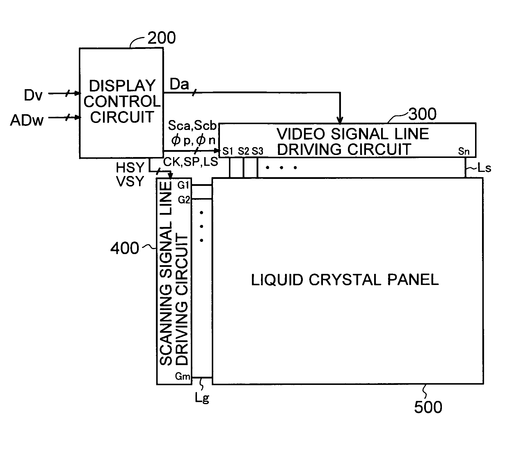
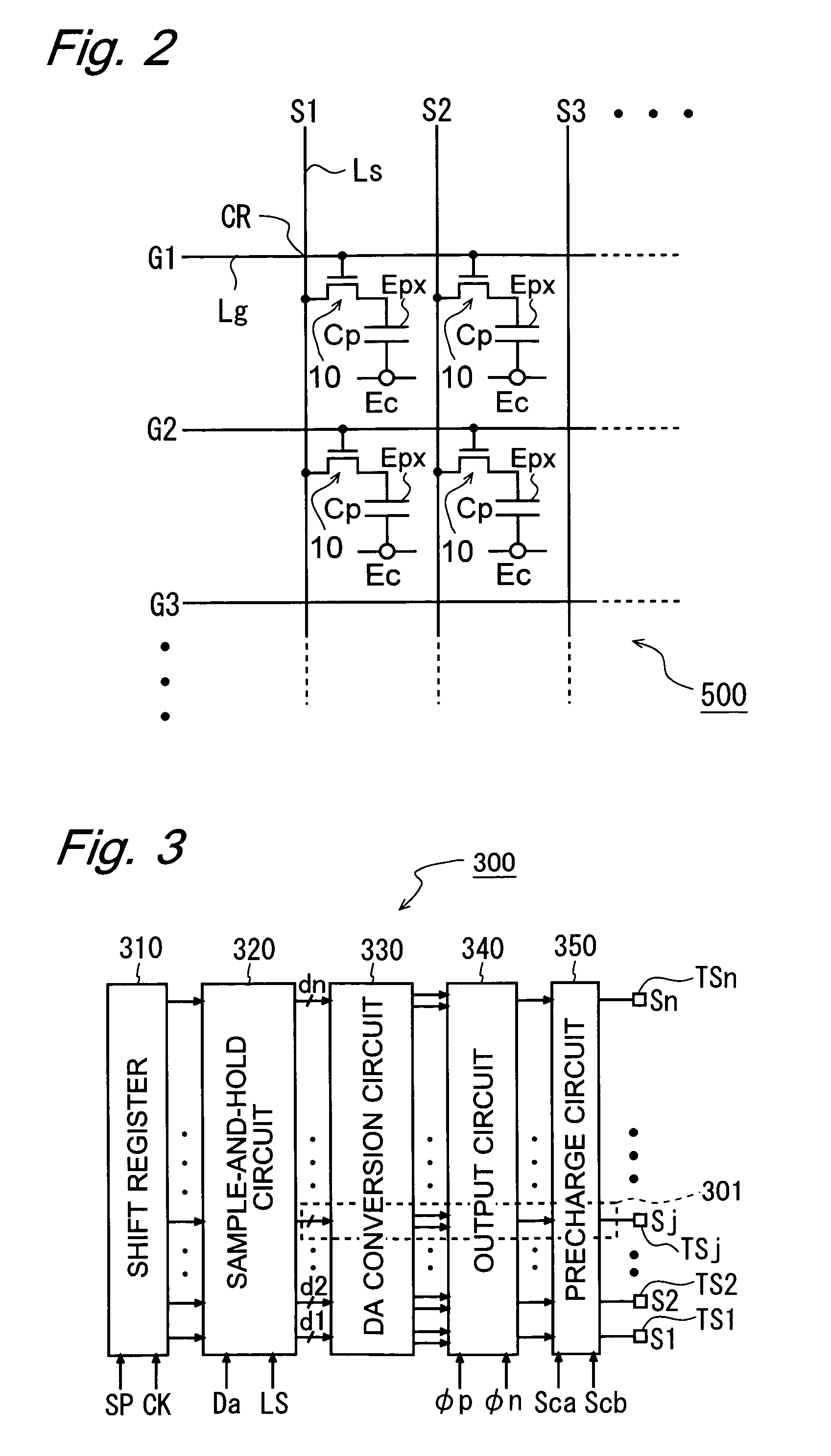
[0120]In the above-described embodiment, a unit precharge circuit 51 is provided for each output terminal TSj (j=1, 2, . . . , n) within the video signal line driving circuit 300. But instead, it is also possible to provide a unit precharge circuit 51 for each video signal line Ls in the liquid crystal panel 500.

[0121]Moreover, in the above-described embodiment, the common electrode Ec of the liquid crystal panel 500 is at a fixed potential (ground level), but instead, the common electrode Ec may also be configured to be AC driven as shown in FIG. 14B. Also with this configuration, due to the operation of the precharge circuit 350 (unit precharge circuit 51) the changes ΔVp and ΔVn of the video signal line potential to be changed by the positive polarity output buffer 41p and the negative polarity output buffer 41n of the video signal line driving circuit 300 become smaller in accordance with the charge voltage at the precharge capacitor Cpr, and the same effe...


PUM

PropertyMeasurementUnit
capacitance C2aaaaaaaaaa
resistanceaaaaaaaaaa
voltageaaaaaaaaaa

Abstract

A video signal line driving circuit includes, for each output terminal TSj, a unit precharge circuit made of a capacitor Cpr and switches SWA1, SWA2, SWB1 and SWB2 for connecting the capacitor Cpr in parallel to a capacitive load of a liquid crystal panel. An OFF period in which first and second output buffers are electrically disconnected from the video signal line is provided between a P period in which a positive voltage is to be applied from the first output buffer in the video signal line driving circuit to the video signal lines (capacitive load) and an N period in which a negative voltage is to be applied from the second output buffer. A first and a second precharge period are set within this OFF period. In the first precharge period, the capacitor Cpr is connected in parallel to the capacitive load of the liquid crystal panel, and in the second precharge period, the capacitor Cpr is connected in parallel to the capacitive load with an orientation that is opposite to the orientation in the first precharge period.

Description

CROSS REFERENCE TO RELATED APPLICATIONS[0001]This application claims priority under 35 U.S.C. §119(a) upon Japanese Patent Application No. 2003-193775 titled “CIRCUIT AND METHOD FOR DRIVING CAPACITIVE LOAD,” filed on Jul. 8, 2003, the content of which is incorporated herein by reference.BACKGROUND OF THE INVENTION[0002]1. Field of the Invention[0003]The present invention relates to driving circuits and driving methods for driving a capacitive load, for example a driving circuit for displaying an image by applying a voltage to a capacitive load, such as an active-matrix liquid crystal panel, as well as to display devices provided with such a driving circuit.[0004]2. Description of the Related Art[0005]Liquid crystal display devices display images by applying a voltage corresponding to an input video signal to each video signal line provided in a liquid crystal panel. That is to say, to display images with the liquid crystal display device, a capacitive load including, for example, th...

Claims


Application Information

Patent Timeline
Patent Type & Authority Patents(United States)
IPC IPC(8): G09G5/00G02F1/133G09G3/20G09G3/36H03K17/51
CPCG09G3/3688G09G3/3614G09G2310/0248G09G2310/027G09G3/36
Inventor INADA, KEN
Owner SHARP KK
Why Eureka
Try Eureka