
Steerable trailer drive assembly

a technology of steering wheel and drive shaft, which is applied in the direction of tractors, wheelchairs/patient conveyancers, cycles, etc., can solve the problems of immobilizing the trailer, difficult trailer alignment in tight locations, and manual repositioning is difficult and tedious, and achieves accurate control of the wheel direction.

Inactive Publication Date: 2008-02-12
TYLER JAMES H
View PDF13 Cites 30 Cited by
  • Summary
  • Abstract
  • Description
  • Claims
  • Application Information

AI Technical Summary

Benefits of technology

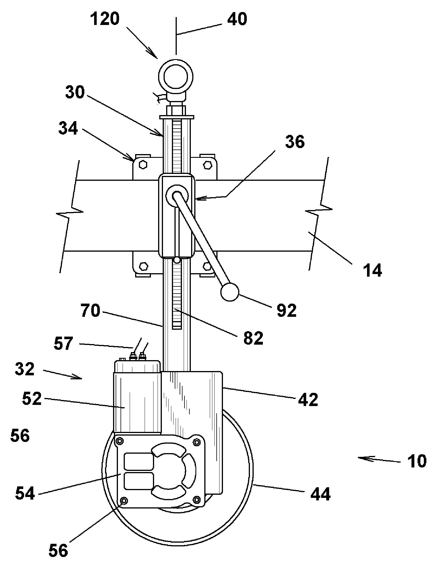
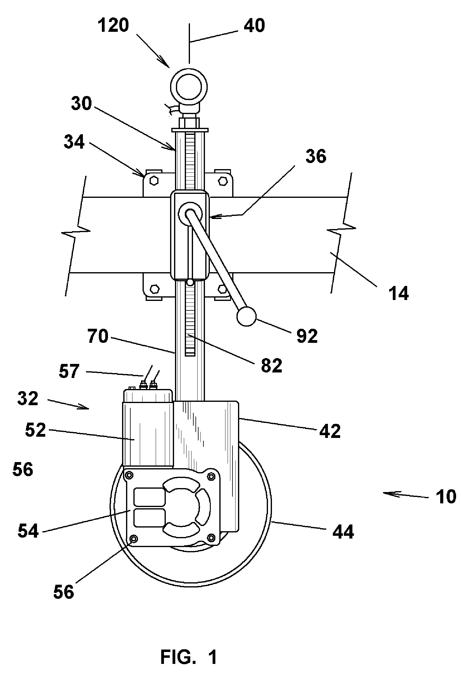
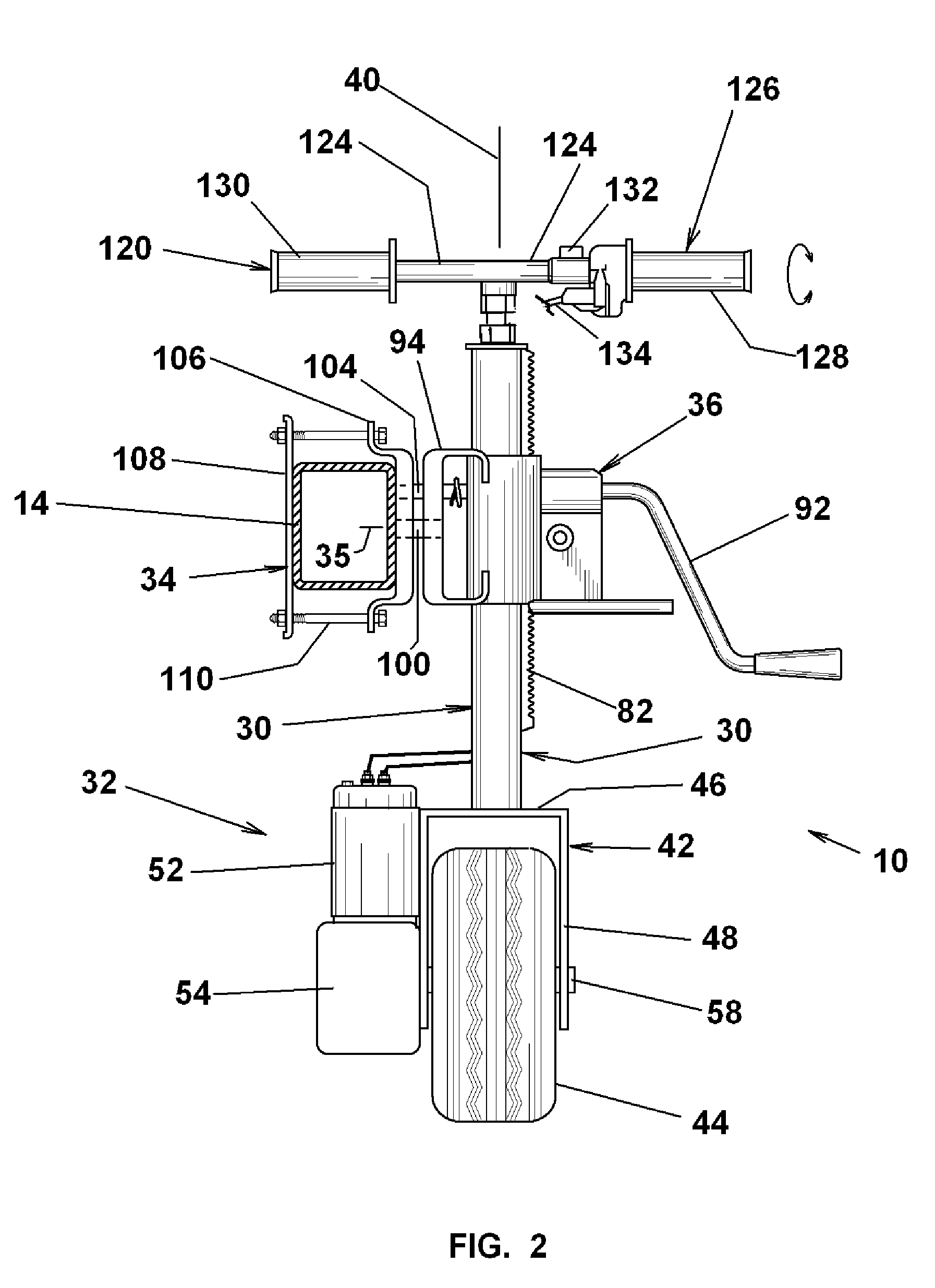
[0005]The present invention provides a compact steerable and motorized drive assembly that may be mounted on a trailer tongue to allow local transfer of the trailer to desired locations after uncoupling from the vehicle. The drive assembly includes a hand throttle controlled, variable speed drive wheel unit operated at an upper steering handle that allows the operator to accurately control wheel direction and wheel speed, without wheel slippage, on all terrain conditions from a normal walk-along position. The drive assembly includes a vertical, pivoting jack assembly that allows raising the trailer tongue from the towing hitch to an operative position for transit. For vehicle towing, the drive assembly may be jacked to a raised position, and optionally pivoted to a horizontal stowed position.
[0007]Another object of the invention is to provide a steerable motorized trailer drive assembly that may be accurately maneuvered under controlled variable speed conditions.
[0008]A further object of the invention is to provide a trailer drive assembly that may be removably incorporated on available trailer tongues without modification of the trailer.

Problems solved by technology

After uncoupling from a towing vehicle, it is oftentimes necessary to reposition to a trailer for storage or unloading at subsequent locations.
The trailer may remain loaded with goods and equipment and accordingly the required manual repositioning is difficult and tedious.
In other instances, the trailer storage location may be congested preventing the towing vehicle from positioning the trailer, and again requiring manual repositioning.
Moreover, the storage or use area may be contoured with unstable terrain composition.
On irregular surfaces, the wheel spin can lead to ruts that immobilize the trailer.
Further, the motor starting torque causes a wheel speed surge resulting in positioning undershoot or overshoot making difficult trailer alignment in tight locations, such as at the hitch.

Method used


Image

  • Steerable trailer drive assembly
  • Steerable trailer drive assembly
  • Steerable trailer drive assembly

Examples


Embodiment Construction

[0017]Referring to FIGS. 3 and 4, a steerable drive assembly 10 is mounted on the tongue 12 of a trailer 14 for self-propelled movement about a terrain 16 and to and from a hitch 18 on a towing vehicle 19. The drive assembly 10 is operatively connected with a control system 20 mounted in a case 22 carried at a convenient location on the trailer 14. The control system 20 includes a battery 24 and a variable speed controller 26 for providing bidirectional speed control of the assembly 10 as described in greater detail below. The drive assembly 10 is vertically adjustable with respect to the tongue 12 to a raised position, not shown, during towing, and to lowered positions shown in FIGS. 1 and 2 to enable coupling and uncoupling with respect to the hitch 18. When uncoupled, the drive assembly 10 provides local transport over the terrain 16 with 360° steering capability and with infinite variable speed control thereby allowing full traverse of the local terrain.

[0018]Referring to FIGS. ...


PUM


Abstract

A steerable drive assembly for local movement of a trailer includes an electric motor drive wheel unit having a drive wheel connected to the output shaft of a gear reduction unit. A steering shaft is connected to the drive wheel unit and an upper operating handle. The steering shaft is rotatably supported by a sleeve assembly that is attached to the tongue of the trailer. The operating handle includes a throttle coupled with the electric motor through a variable speed control for providing progressing power to the motor to enable speed variation without wheel slippage.

Description

RELATED APPLICATION[0001]This application claims the benefit of U.S. Provisional Application No. 60 / 602,386 filed on Aug. 18, 2004.FIELD OF THE INVENTION[0002]The present invention relates to a motorized assembly for maneuvering a trailed vehicle from a hitched condition with a towing vehicle to an alternative location.BACKGROUND OF THE INVENTION[0003]After uncoupling from a towing vehicle, it is oftentimes necessary to reposition to a trailer for storage or unloading at subsequent locations. The trailer may remain loaded with goods and equipment and accordingly the required manual repositioning is difficult and tedious. In other instances, the trailer storage location may be congested preventing the towing vehicle from positioning the trailer, and again requiring manual repositioning. Moreover, the storage or use area may be contoured with unstable terrain composition.[0004]Various motorized devices have been proposed for moving trailed vehicles to and from the towing vehicle. Elec...

Claims


Application Information

Patent Timeline
IPC IPC(8): B62M7/14
CPCB60S9/215B62D59/04
Inventor TYLER, JAMES H.
Owner TYLER JAMES H
Learn More