
Logically partitioned computer system and method for controlling configuration of the same

a computer system and partition technology, applied in multi-programming arrangements, fault response, instruments, etc., can solve problems such as insufficient performance covered by running plural logical computers in parallel, computer resources consumed for unpredictable failures, and computer resources consumed

Inactive Publication Date: 2008-02-05
HITACHI LTD
View PDF13 Cites 32 Cited by
  • Summary
  • Abstract
  • Description
  • Claims
  • Application Information

AI Technical Summary

Problems solved by technology

Conventionally, insufficient performance has been covered by running plural logical computers in parallel.
According to this method, since standby logical computers are provided in advance for hot standby, computer resources are consumed for unpredictable failures.
According to this method, although failures are predicted, the device is assumed to be duplexed, and still computer resources are consumed.

Method used


Image

  • Logically partitioned computer system and method for controlling configuration of the same
  • Logically partitioned computer system and method for controlling configuration of the same
  • Logically partitioned computer system and method for controlling configuration of the same

Examples


first embodiment

[0026]Hereinafter, a first embodiment of a method for achieving a highly reliable multiple system according to the present invention will be described in detail with reference to the drawings.

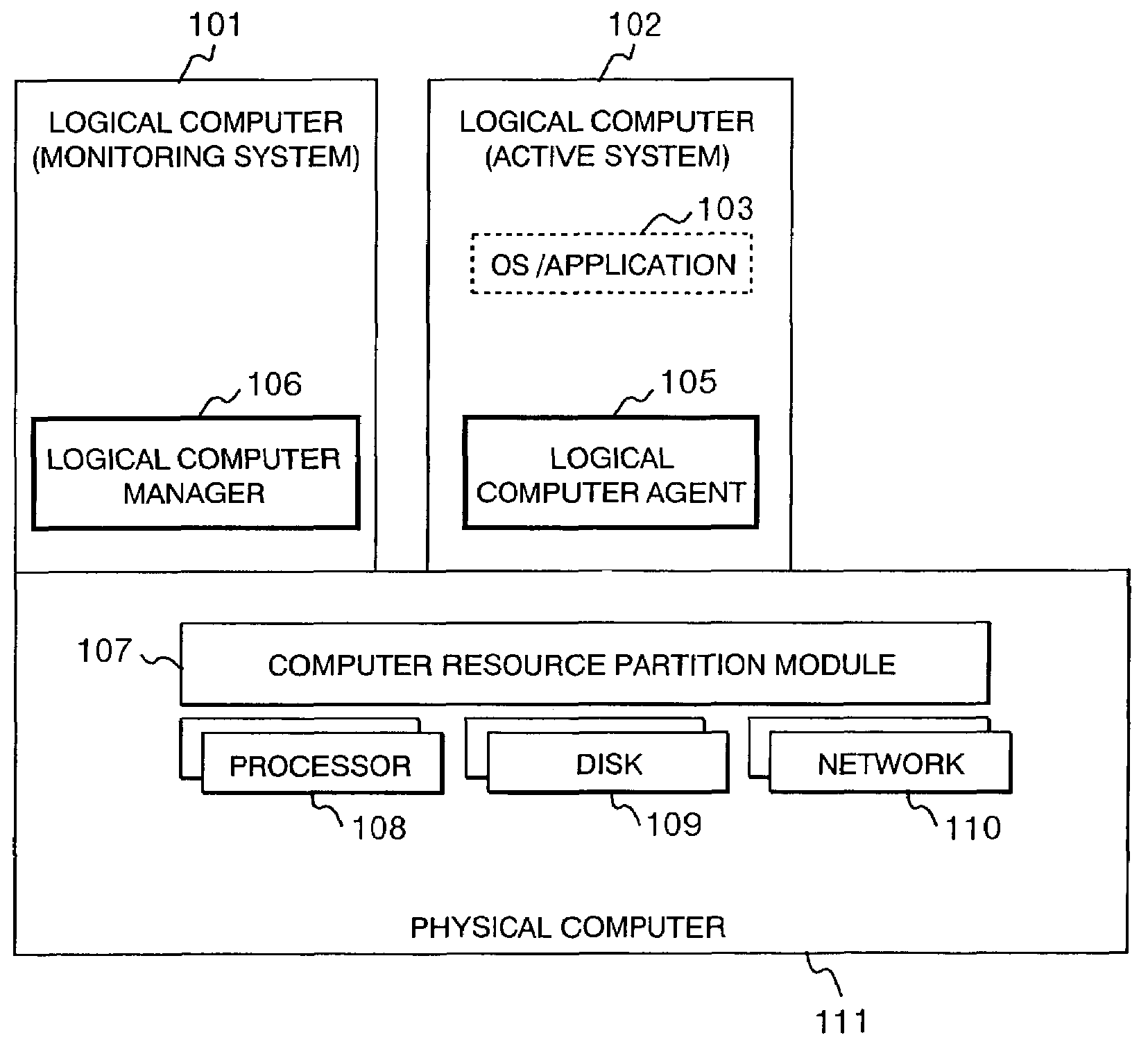
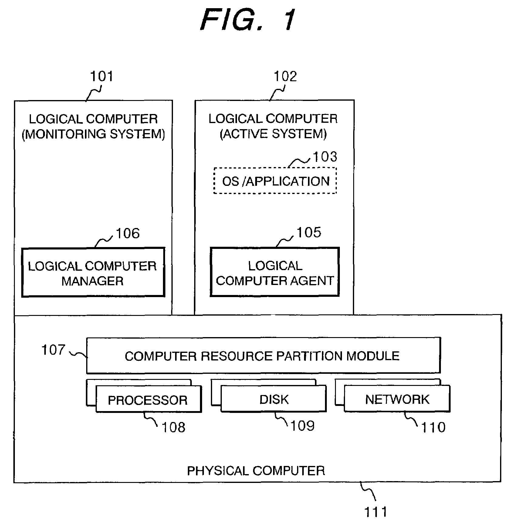
[0027]FIG. 1 shows a schematic diagram of a method for achieving a highly reliable multiple system according to the present invention. The reference numerals 101 and 102 indicate logical computers, respectively, and 111 indicates a physical computer. The physical computer 111 comprises a physical processor 108, a disk unit 109, a network device 110, and a computer resource partitioning module 107.

[0028]The logical computers 101 and 102 are virtual computers created from resources of the physical computer 111. Although not shown, plural logical computers of active systems are generally created. That is, generally, one monitoring system is provided for plural active systems. Each of the processor 108, disk unit 109, network device 110 possessed by the physical computer 111 is split for assignment...

second embodiment

[0046]Although, in the above-described embodiment, failures are predicted based on log messages outputted by an OS and applications, a failure prediction method will be described from a different standpoint in another embodiment.

[0047]FIG. 12 shows an example of a failure prediction level definition table used to predict failures by monitoring the operating time of logical computers. As the thresholds of failure prediction determination, the operating time of logical computers (column 1201) is set.

[0048]Prolonged operating time of computers and application programs may slow down processing and increase the possibility of system failures due to fragmentary management of computer resources and reduction in an available resource amount attributed to software bugs. This embodiment enables periodic system refresh in such a case.

[0049]Likewise, FIG. 13 shows an example of a failure prediction level definition table used to predict failures by monitoring the service contents of application...


PUM


Abstract

High reliability is achieved using logical computers without having to provide logical computers for a standby system in advance. By monitoring a status of an active system to predict failures, standby logical computers are newly created to switch logical computers running the system.

Description

BACKGROUND OF THE INVENTION[0001]1. Field of the Invention[0002]The present invention relates to an increase in reliability against failures in a system using logical computers.[0003]2. Description of the Prior Art[0004]The advance of processor technology has enabled high-performance processors to be easily used. Conventionally, insufficient performance has been covered by running plural logical computers in parallel. With the advent of high-performance processors, however, performance has been satisfied and concerns are shifting to how to effectively use the high-performance processors. A logical computer function is one approach to the effective use of the high-performance processors. The logical computer function is technology for creating plural virtual computers from one physical computer.[0005]For example, by assigning one physical processor to plural logical computers in a timesharing mode, software running on the logical computers can operate as if different physical compute...

Claims


Application Information

Patent Timeline
Patent Type & Authority Patents(United States)
IPC IPC(8): G06F11/00G06F11/20G06F9/46G06F9/48G06F11/30G06F11/32G06F11/34
CPCG06F11/0712G06F11/076G06F11/1484G06F11/3476G06F11/1482G06F11/324
Inventor UKAI, TOSHIYUKITAKAMOTO, YOSHIFUMI
Owner HITACHI LTD
Learn More