
Relay apparatus for relaying communication from CPU to peripheral device

a technology of relay apparatus and peripheral device, which is applied in the field of peripheral circuits, can solve the problems of increasing the workload of cpu, reducing the performance of the entire system, and increasing the demands for more complex processing, so as to reduce the overhead of cpu

Inactive Publication Date: 2008-02-05
CANON KK
View PDF16 Cites 0 Cited by
  • Summary
  • Abstract
  • Description
  • Claims
  • Application Information

AI Technical Summary

Benefits of technology

The present invention provides a way for a peripheral device to communicate with another peripheral device quickly and efficiently using burst-mode communication. This reduces the workload of the central processing unit (CPU) and simplifies the firmware. The invention includes a relay apparatus or a timing pulse generation device that holds information and commands for communication with the peripheral devices and performs the communication based on the commands. This allows for easy setting of parameters and writing of commands, reducing the CPU overhead and simplifying the system start-up and changes.

Problems solved by technology

In electronic systems such as digital cameras, there have been increasing demands for more complex processing.
When such complex processing is to be performed by a single CPU, the load on the CPU increases, and the performance of the entire system thus decreases.
However, if a large number of CPUs are installed to distribute the processing, the cost increases.
For this reason, when an operation is performed with a communication rate matching a peripheral device, communication from the CPU to the peripheral device becomes an overhead of the system, and a side effect, such as a time lag in the shutter operation, appears.
For this reason, firmware for performing serial communication with the peripheral device 502 becomes complex in the CPU, and also, the communication takes time, and an overhead occurs.

Method used


Image

  • Relay apparatus for relaying communication from CPU to peripheral device
  • Relay apparatus for relaying communication from CPU to peripheral device
  • Relay apparatus for relaying communication from CPU to peripheral device

Examples


Embodiment Construction

[0029]Exemplary embodiments of the present invention will be described below in detail with reference to the drawings.

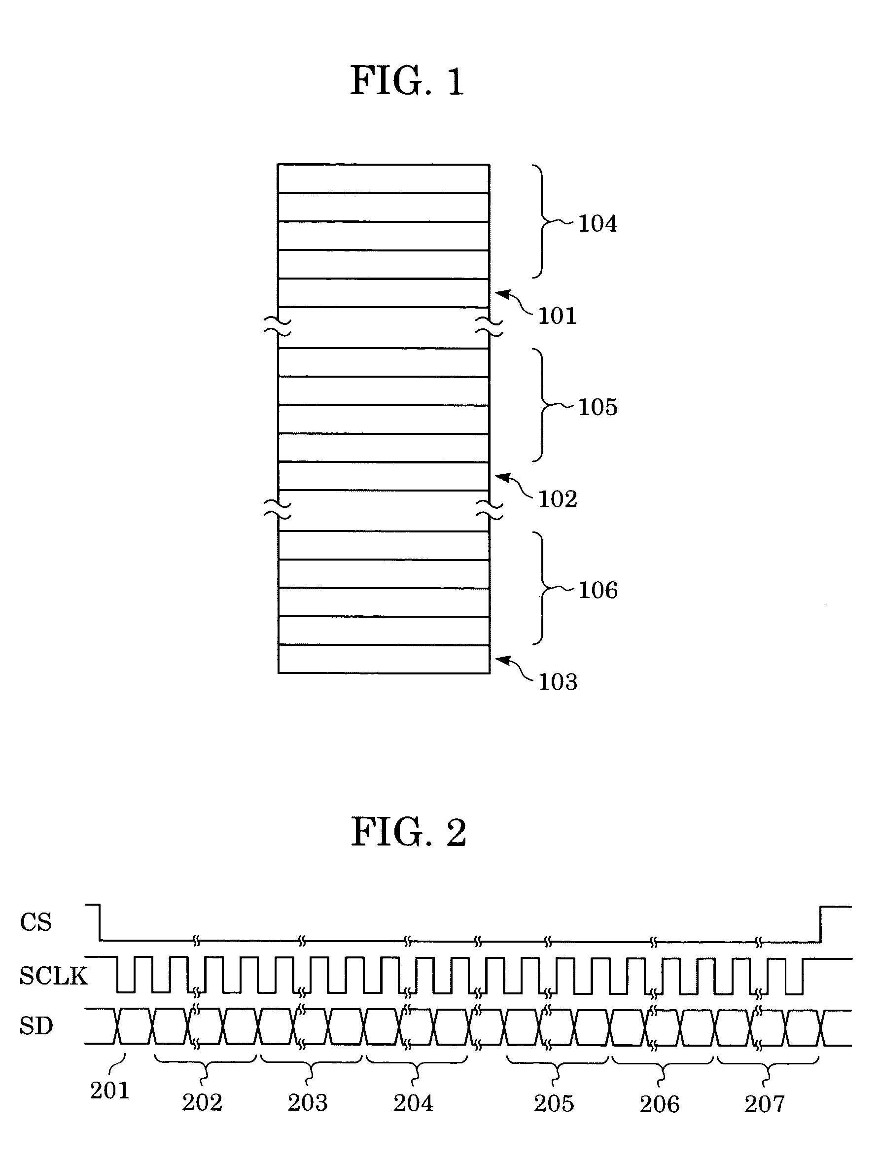
[0030]FIG. 1 shows an embodiment of the present invention, and also shows the configuration of internal registers of a peripheral device (relay apparatus) for taking over communication from a CPU to another peripheral device.

[0031]Referring to FIG. 1, a first register group 104 holds parameters of the peripheral device requiring communication from the CPU. A first command register 101 holds a command for instructing the execution of communication. A second register group 105 holds parameters of a second peripheral device. A second command register 102 holds a command for instructing the execution of communication. A third register group 106 holds parameters of a third peripheral device requiring communication from the CPU. A third command register 103 holds a command for instructing the execution of communication. A description is given with reference to the configur...


PUM


Abstract

In order to reduce overhead of a CPU, a relay apparatus for relaying communication from a CPU to a peripheral device includes communication information holding sections for holding information required for communication with the peripheral devices inside the relay apparatus; and command holding sections, which are provided adjacent to the communication information holding section, for holding commands used to communicate desired information inside the communication information holding section to the peripheral device. The CPU writes desired information in the communication information holding section and the command holding section inside the relay apparatus by burst-mode communication, and the relay apparatus performs communication with the peripheral devices in accordance with instructions from the command holding section after the writing of the desired information in the communication holding section and the command holding section is completed.

Description

BACKGROUND OF THE INVENTION[0001]1. Field of the Invention[0002]The present invention relates to a peripheral circuit that operates in accordance with instructions from a CPU. More particularly, the present invention relates to the implementation of a register for writing commands inside an apparatus for performing a desired operation by receiving an instruction from a CPU.[0003]2. Description of the Related Art[0004]In electronic systems such as digital cameras, there have been increasing demands for more complex processing. When such complex processing is to be performed by a single CPU, the load on the CPU increases, and the performance of the entire system thus decreases. However, if a large number of CPUs are installed to distribute the processing, the cost increases. For this reason, it is common practice that the electronic system is formed of a CPU and peripheral devices that perform complex operations in accordance with simple commands from the CPU. In such an electronic sy...

Claims


Application Information

Patent Timeline
Patent Type & Authority Patents(United States)
IPC IPC(8): G06F13/00G06F3/00G06F13/42
CPCG06F13/4291
Inventor TATENO, TETSUYA
Owner CANON KK
Learn More