
AC generator and method

a generator and alternating current technology, applied in current collectors, dynamo-electric components, mechanical energy handling, etc., can solve problems such as efficiency loss, and achieve the effects of reducing the effect of secondary magnetic fields, reasonable expense, and good efficiency

Inactive Publication Date: 2008-02-05
NULLGRAV
View PDF18 Cites 9 Cited by
  • Summary
  • Abstract
  • Description
  • Claims
  • Application Information

AI Technical Summary

Benefits of technology

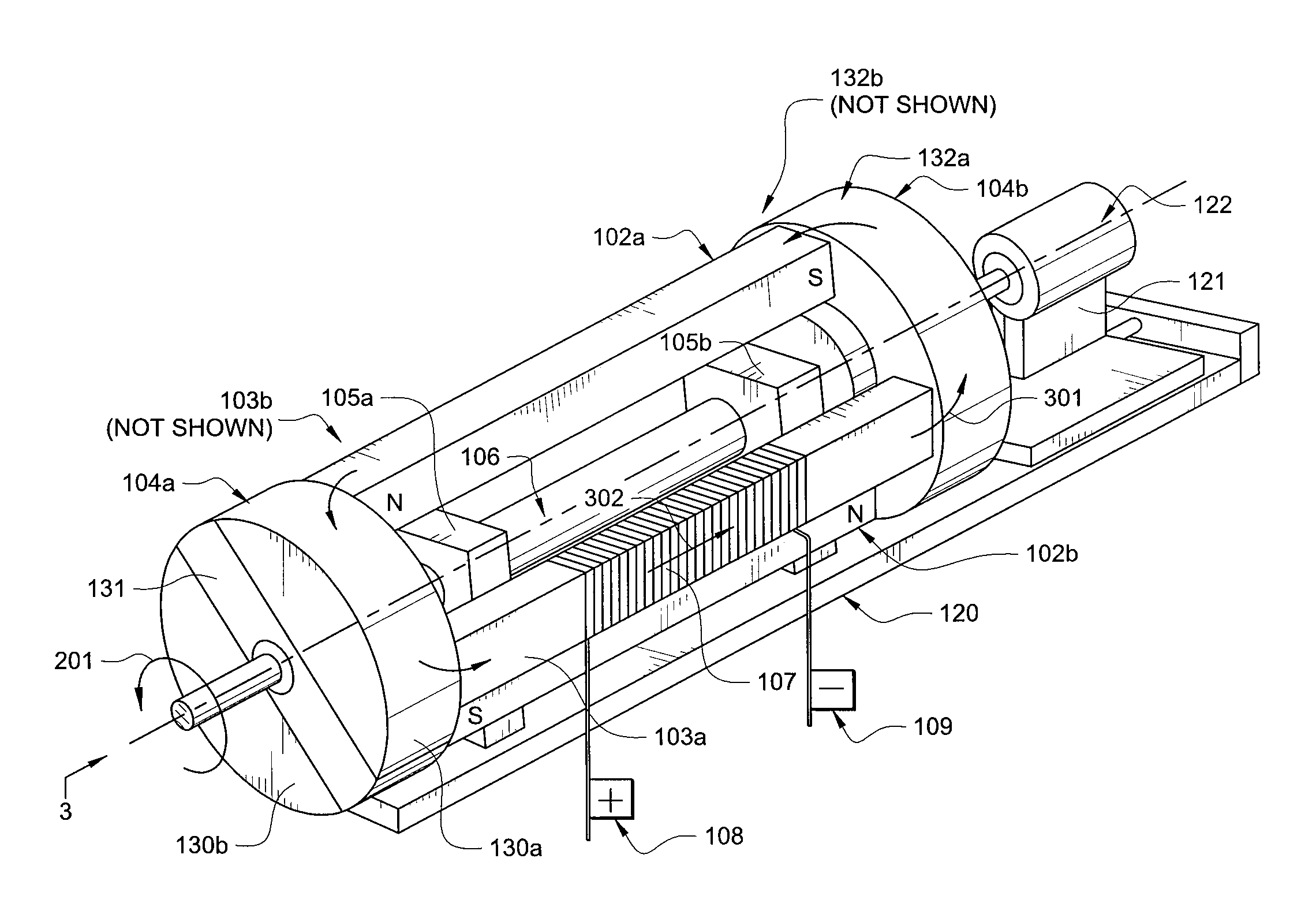
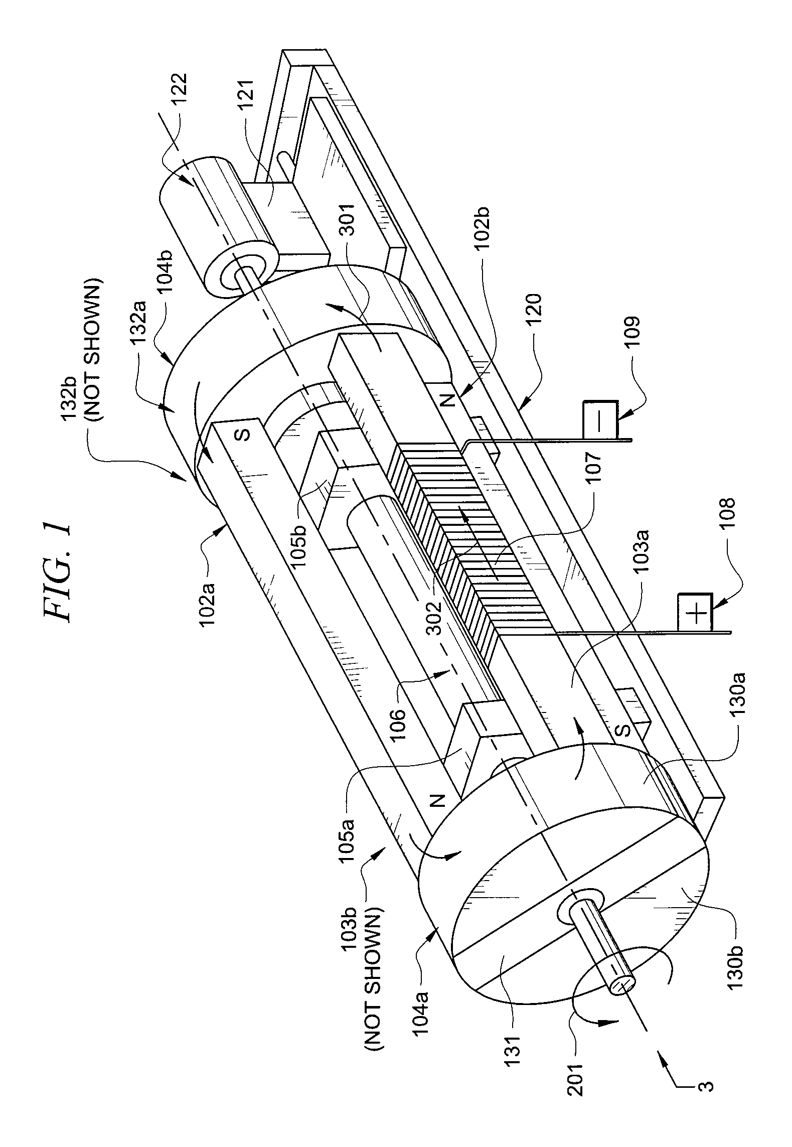
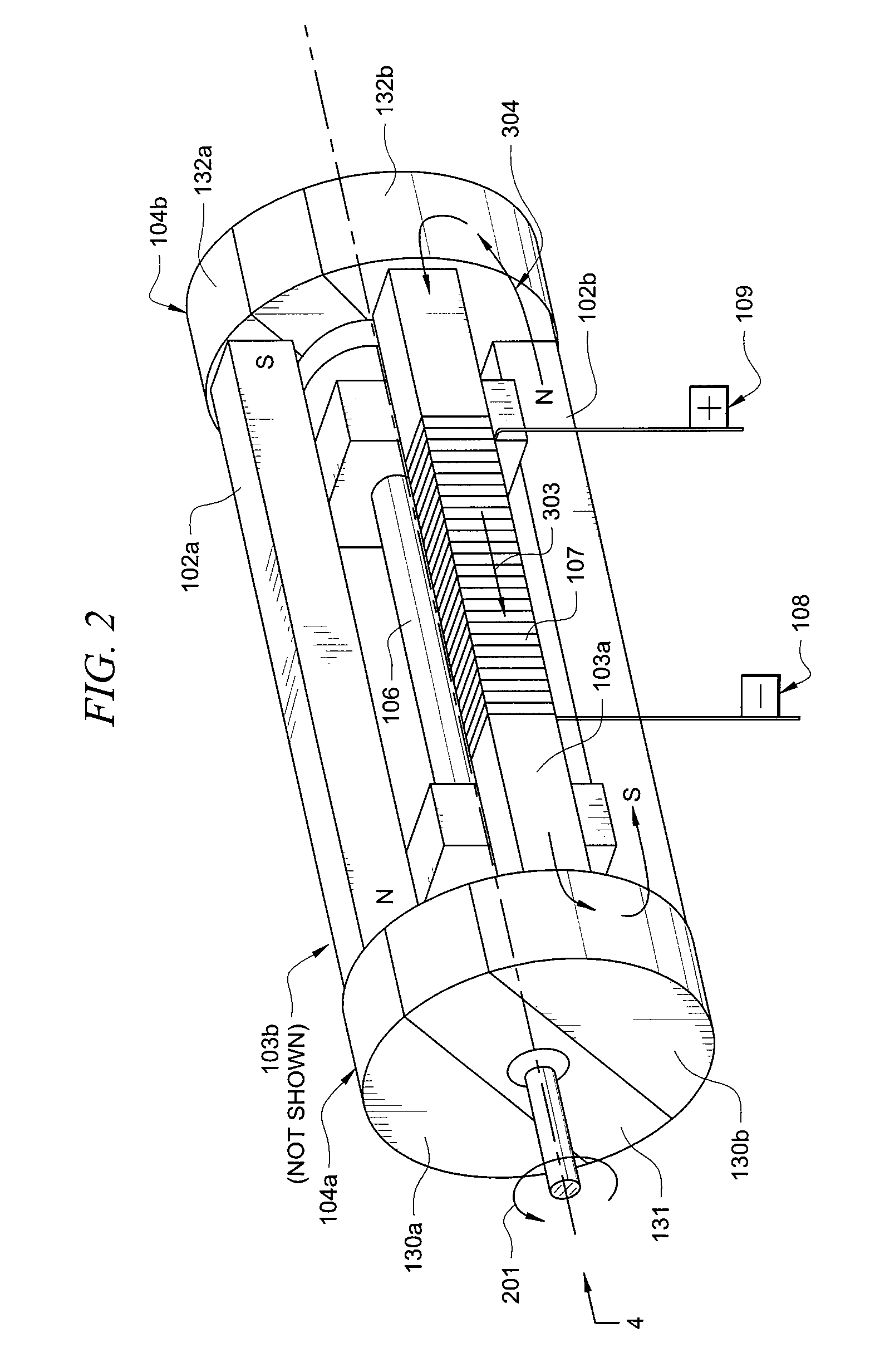
"The invention is a generator with two commutators mounted on a rotating shaft, and two magnetically conductive bars that pass through a wire coil. The generator has magnets that change their magnetic field due to the rotation of the shaft, which induces current into the wire coil. The technical effects of this invention include a small number of components, low cost, good efficiency, and reduced interference between secondary magnetic fields. Additionally, adjustment methods may be provided to increase efficiency by reducing air gaps between the commutators and bars / magnets."

Problems solved by technology

In conventional AC generators, efficiency is lost due to the loss of magnetic flux transference due to air gaps between moving parts of a magnetic toroid, and due to rotation resistance due to magnetic attraction and repulsion forces while generating alternating current electricity.

Method used


Image

  • AC generator and method
  • AC generator and method
  • AC generator and method

Examples


Embodiment Construction

[0014]The preferred embodiment of the present invention and its advantages are best understood by referring to FIGS. 1 through 8 of the drawings, like numerals being used for like and corresponding parts of the various drawings.

[0015]The disclosed apparatus may be used to generate AC-electricity. It may include a mounting base to which may be attached (either directly or indirectly), two or more bearing blocks, two or more magnets and two magnetically conductive bars with wire coils wrapped about them. The bearings may allow a rotating shaft to pass through them, which may have multiple commutators mounted thereon. The commutators (as the term is used in this document) may have two or more magnetically conductive sections within a disk (or other) shape, and these sections may be symmetrical (or asymmetrical). The conductive sections of a commutator may line up with substantially equivalent sections of another commutator on the shaft.

[0016]As the commutators and shaft rotate, the mag...


PUM


Abstract

One aspect of the invention is a generator with at least two commutators mounted on a rotatable shaft. At least two magnetically conductive bars may be mounted in an opposed relationship with at least one of the bars passing through a wire coil. At least two magnets may also be mounted in an opposed relationship. The bars and magnets may be mounted such that they extend between the commutators. In various positions, a magnetic field passes through the two commutators, one of the bars and one of the magnets. The magnet field in the bars changes due to rotation of the shaft and current is induced into the wire coil.

Description

TECHNICAL FIELD OF THE INVENTION[0001]This invention relates generally to the generation of alternating current (AC) electricity and more particularly to an improved AC generator.BACKGROUND OF THE INVENTION[0002]In conventional AC generators, efficiency is lost due to the loss of magnetic flux transference due to air gaps between moving parts of a magnetic toroid, and due to rotation resistance due to magnetic attraction and repulsion forces while generating alternating current electricity.SUMMARY OF THE INVENTION[0003]One aspect of the invention is a generator with at least two commutators mounted on a rotatable shaft. At least two magnetically conductive bars may be mounted in an opposed relationship with at least one of the bars passing through a wire coil. At least two magnets may also be mounted in an opposed relationship. The bars and magnets may be mounted such that they extend between the commutators. In various positions, a magnetic field passes through the two commutators,...

Claims


Application Information

Patent Timeline
Patent Type & Authority Patents(United States)
IPC IPC(8): H02K7/20
CPCH02K21/44
Inventor ROGALA, RICHARD L.
Owner NULLGRAV
Learn More