


Quick Research
Generate reliable direction feasibility study reports for your R&D in just a few steps.

Technical Q&A
Discover and master advanced knowledge NOW. Basics, ideas, possibilities, all at once.

Find Solutions
As an expert in R&D theories, this can generate solutions to your technical problems instantly.

Evaluate Feasibility
Analyze your overall solution with one click, know your potential R&D risks in advance.

Monitor Landscape
Get weekly tech updates, stay abreast of the latest tech innovations and key insights.
Modular infeeds for automatic forms/fill/seal equipment
a module and equipment technology, applied in the direction of packaging foodstuffs, packaging goods, transportation and packaging, etc., can solve the problem that machines do not facilitate a rapid changeover from one to the other
- Summary
- Abstract
- Description
- Claims
- Application Information
AI Technical Summary
Benefits of technology
Problems solved by technology
Method used
Image

Examples
Embodiment Construction
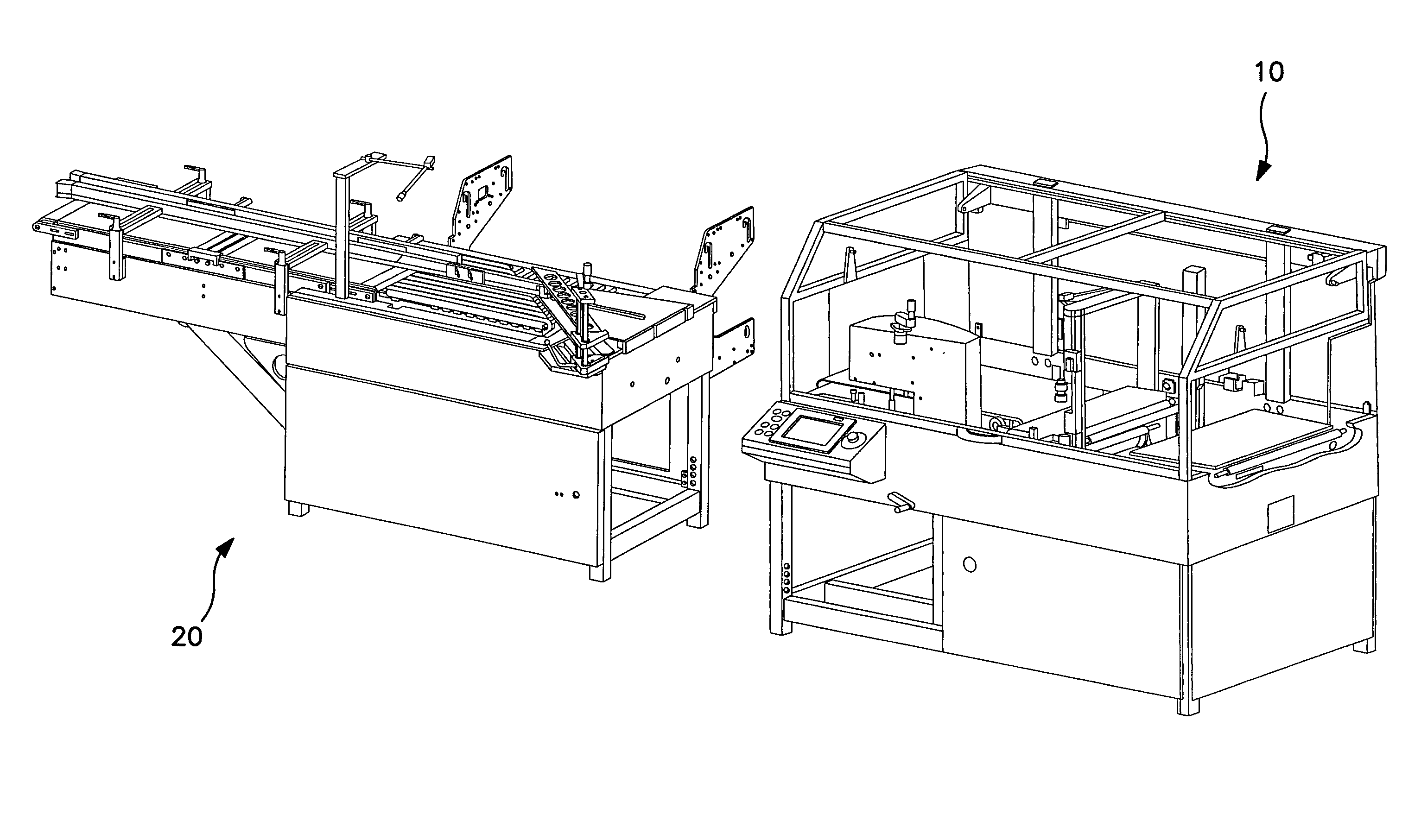
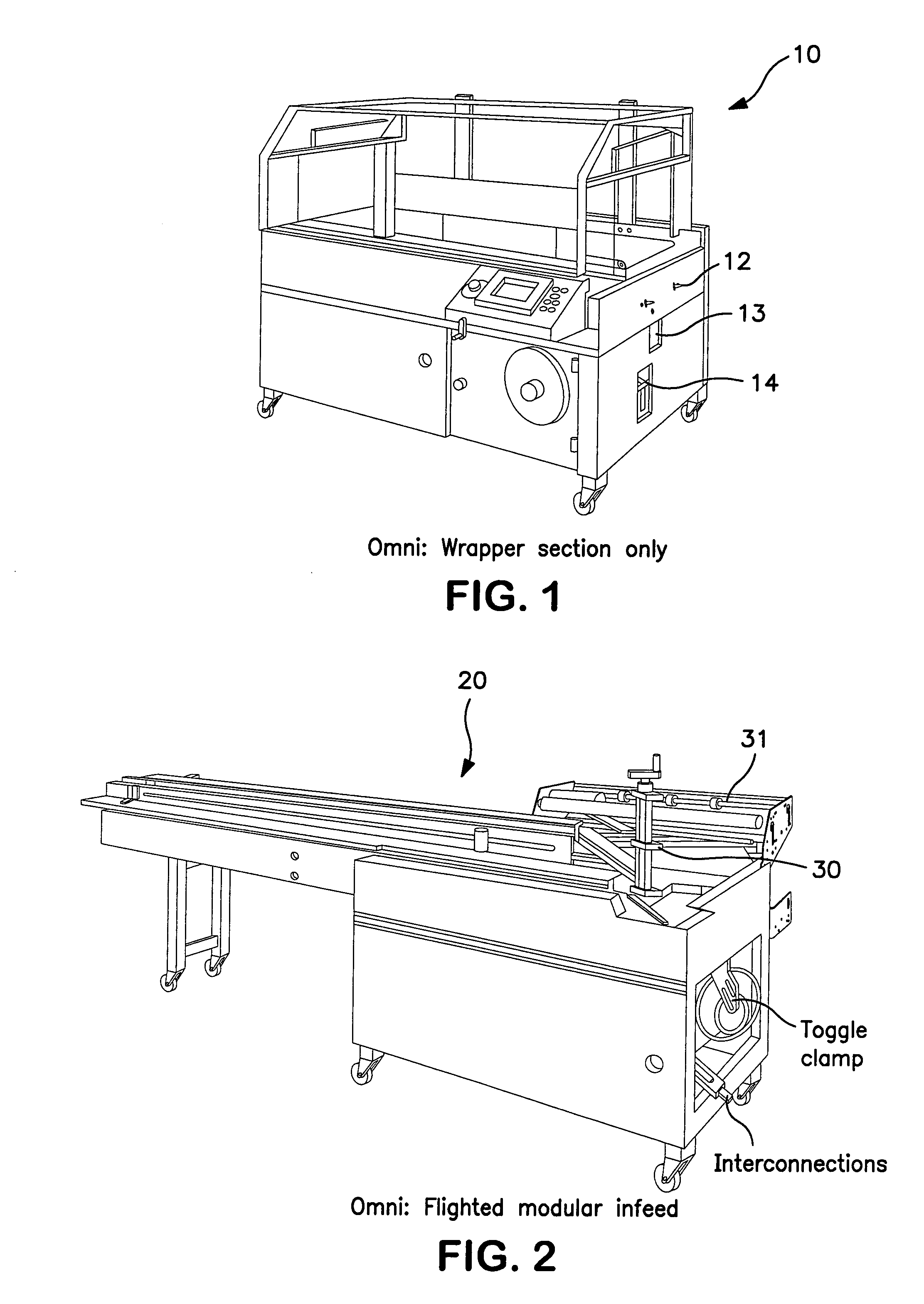
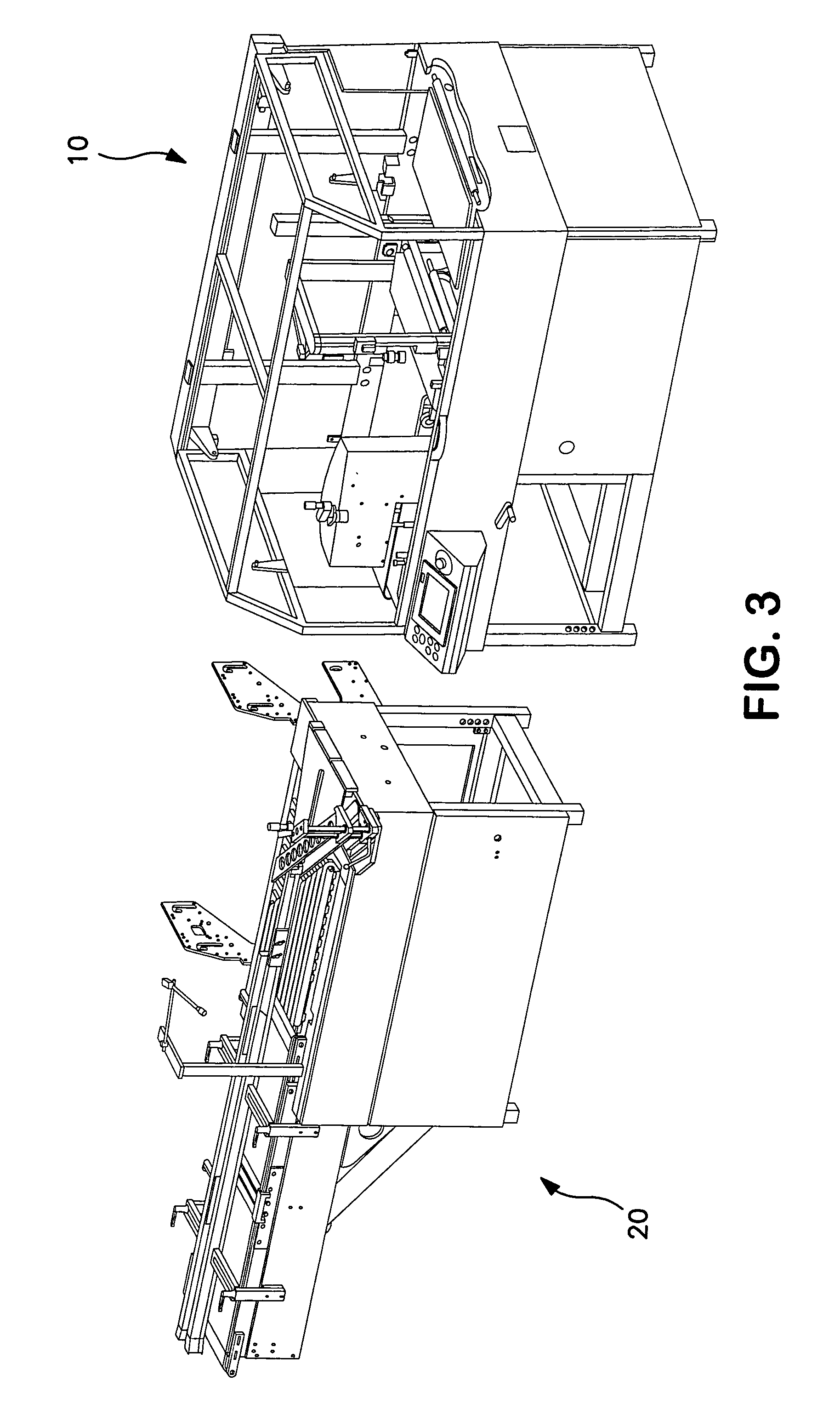
[0014]Turning now to FIG. 1, there is shown generally at 10 a wrapping section of a packaging machine. The wrapping equipment is generally conventional, except that it preferably does not include film unwind assembly or a film inverting head, as these components are now preferably included on the modular infeed assembly as discussed in greater detail below. Furthermore, the wrapping section 10 also differs from conventional designs in that it includes suitable connecting points and alignment members for readily attaching and detaching a modular infeed. Thus, one or more locating / aligning members 12 (two shown) are provided on the product-input end of the machine to assist in properly aligning the modular infeed with the wrapper. Similarly, a toggle connection 13 or the like is located at the product-input end to lock the modular infeed to the wrapper, as is an interconnection port 14 described in greater detail below.
[0015]FIGS. 2, 4A and 4B illustrate examples of modular infeed uni...
PUM
| Property | Measurement | Unit |
|---|---|---|
| flexible | aaaaa | aaaaa |
| speeds | aaaaa | aaaaa |
| size | aaaaa | aaaaa |
Abstract
Description
Claims
Application Information
 - R&D Engineer
- R&D Manager
- IP Professional
- Industry Leading Data Capabilities
- Powerful AI technology
- Patent DNA Extraction
Browse by: Latest US Patents, China's latest patents, Technical Efficacy Thesaurus, Application Domain, Technology Topic, Popular Technical Reports.
© 2024 PatSnap. All rights reserved.Legal|Privacy policy|Modern Slavery Act Transparency Statement|Sitemap|About US| Contact US: help@patsnap.com