Optical code division multiplex transmission method and optical code division multiplex transmission device

a transmission method and optical code technology, applied in the field of optical code division multiplex transmission method and optical code division multiplex transmission device, can solve the problems of limited wavelength bands which can be transmitted by the optical fiber which is the transmission path, the limit of the multiplexing density of a dwdm system, and the limited wavelength bandwidth of optical carrier waves, etc., to achieve shorten the effective lattice interval, shorten the grating interval, and achieve the effect of shortening the effective la

Active Publication Date: 2008-01-29
MARVELL ASIA PTE LTD
View PDF1 Cites 15 Cited by
  • Summary
  • Abstract
  • Description
  • Claims
  • Application Information

AI Technical Summary

Benefits of technology

[0020]On the other hand, if the ambient temperature and other conditions are different for the encoder and decoder on the transmitting side and receiving side respectively, then a signal encoded by the encoder is not decoded as the same signal as the signal prior to decoding. That is, the decoded optical pulse is distorted. In this case, if the extent of the eye opening of optical pulses output from the second SSFBG which is the decoder are measured by the correlation waveform monitor, then the extent of the eye opening is small compared with the case in which, as described above, the optical pulse waveform is decoded without distortion.

Problems solved by technology

However, in a DWDM system which realizes this method, because the wavelength bandwidths of usable optical carrier waves are finite, there is a limit to the multiplexing density of a DWDM system.
The wavelength bandwidths of optical carrier waves are limited by the fact that the oscillation wavelength band of the semiconductor laser which is the light source generating the optical carrier wave is limited, and by the fact that the wavelength bands which can be transmitted by the optical fiber which is the transmission path are limited.
Also, when the wavelength intervals of the optical carrier waves allocated among channels are narrowed, overlap of the optical spectra between adjacent channels (also called “crosstalk”) may cause the problem of degradation of transmitted optical pulse signals.
Further, when installing an SSFBG in an encoder or decoder, it is in actuality difficult to perform installation such that the operating characteristics of the SSFBGs comprised by the encoder and decoder are the same.
In transmission by phase encoding OCDM, if the operating wavelength of the SSFBG comprised by the transmitting-side encoder and the operating wavelength of the SSFBG comprised by the receiving-side decoder deviate by several tens of pm or more, satisfactory decoding on the receiving side is not possible.
Further, during transmission or reception operation, an encoder or decoder may be affected by the ambient temperature or other changes in the environment, so that the operating wavelength changes.

Method used


Image

  • Optical code division multiplex transmission method and optical code division multiplex transmission device
  • Optical code division multiplex transmission method and optical code division multiplex transmission device
  • Optical code division multiplex transmission method and optical code division multiplex transmission device

Examples


first embodiment

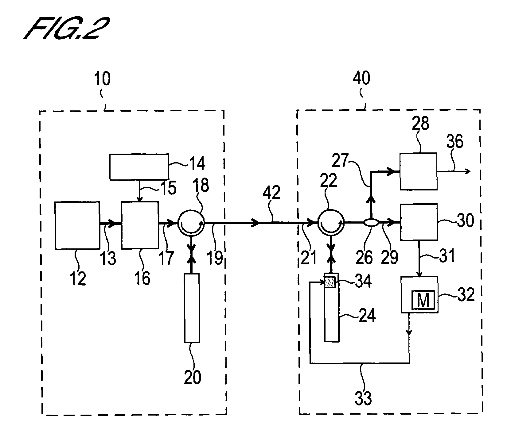
[0085]With reference to the block diagram shown in FIG. 2, an optical code division multiplex transmission method which is a first embodiment of the present invention is explained, together with the configuration of an optical code division multiplex transmission device and functions of each portion of same.

[0086]The optical code division multiplex transmission device comprises a transmitting portion 10 and a receiving portion 40, connected by a transmission path 42. Signals transmitted by this optical code division multiplex transmission device are optical pulse signals; the optical pulse signals are signals obtained by opto-electrical conversion of binary digital electrical pulse signals carrying information to be transmitted (these signals are pulse signals in which the binary digital signal values “0” or “1” are represented by high and low voltages).

[0087]The transmitting portion 10 is configured comprising an optical pulse train generator 12, modulation signal generator 14, opt...

second embodiment

[0148]With reference to the block diagram shown in FIG. 8, an optical code division multiplex transmission method and the configuration of an optical code division multiplex transmission device which are a second embodiment of the present invention are explained, together with the functions of portions thereof. In the following, explanations of portions which are redundant with the optical code division multiplex transmission method and the optical code division multiplex transmission device which are the first embodiment, and with the functions of portions thereof, are omitted.

[0149]The optical code division multiplex transmission device which is the second embodiment of the present invention also comprises a transmitting portion 10 and receiving portion 140, which are connected by a transmission path 42; the transmitting portion 10 is configured comprising an optical pulse train generator 12, modulation signal generator 14, optical modulator 16, first optical circulator 18, and en...


PUM

PropertyMeasurementUnit
Bragg reflection wavelengthaaaaaaaaaa

Abstract

An object of the present invention is to adjust the operating wavelength of a decoder, in order to coordinate the operating characteristics of an encoder and the decoder. To this end, an optical code division multiplex transmission device of the present invention comprises a second SSFBG in the decoder, and has a mechanism to perform adjustment (phase adjustment step) of the fixation portion interval L which is the interval between a first and second fixation portions fixing in place the second SSFBG, such that the extent of the eye opening of optical pulses output from the second SSFBG is maximum. The extent of the eye opening is measured using a correlation waveform monitor, and the measurement data is sent to the wavelength control portion. A signal is sent from the wavelength control portion to the movement control portion to set the fixation portion interval L, based on data relating to the extent of the eye opening sent from the correlation waveform monitor.

Description

BACKGROUND OF THE INVENTION[0001]1. Field of the Invention[0002]The present invention relates to a method of encoding and decoding optical pulse signals in optical code division multiplex transmission, and to a device to realize this method.[0003]2. Description of Related Art[0004]In recent years communication demands have expanded rapidly with the spread of the Internet and other developments. In order to cope with this, high-speed large-capacity networks employing optical fibers and similar are being prepared. In order to construct such high-speed and large-capacity optical networks, wavelength division multiplexing (WDM) transmission methods are indispensable. In particular, so-called dense wavelength division multiplexing (DWDM) methods, in which the wavelength intervals of optical carrier waves assigned to different channels are narrowed and dense wavelength multiplexing on the wavelength axis is employed, are attracting attention.[0005]However, in a DWDM system which realizes ...

Claims


Application Information

Patent Timeline
Patent Type & Authority Patents(United States)
IPC IPC(8): H04J14/00H04B10/516G02B6/02G02F2/00H04B10/07H04B10/2507H04B10/61H04J13/00H04J14/04H04J14/06
CPCG02B6/022H04J14/005H04J14/00G02F2/00
Inventor KOBAYASHI, SHUKONISHIKI, AKIHIKOKUTSUZAWA, SATOKO
Owner MARVELL ASIA PTE LTD
Why Eureka
Try Eureka