
Disk drive, storage medium, and portable precision device

Inactive Publication Date: 2008-01-29
WESTERN DIGITAL TECH INC
View PDF12 Cites 9 Cited by
  • Summary
  • Abstract
  • Description
  • Claims
  • Application Information

AI Technical Summary

Benefits of technology

[0010]The present invention has been made to solve the foregoing technical problems and it is therefore an object of the present invention to provide a disk drive having significantly improved shock resistance.
[0015]Preferably, the disk drive further comprises a connector that is inserted in a slot formed in the object when the disk drive is mounted on the object, and the connector serves as part of the guide function, which forms a positioning part of the guide function without requiring additional parts and reduces the tolerance on the dimension of the assembly. In addition, the thickness of the case assembly in the direction of the frame bumper is dependent on a nut.
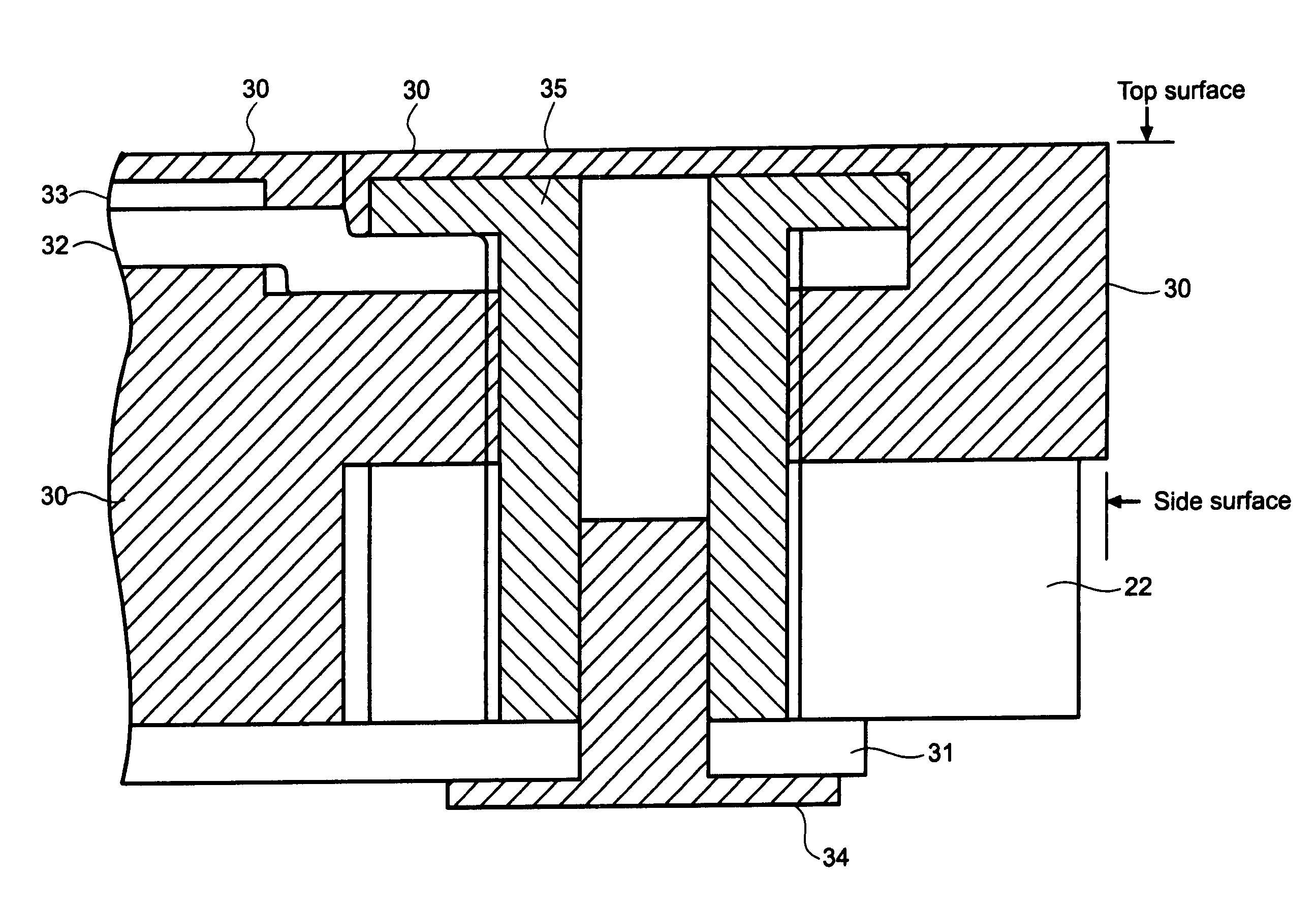
[0017]In the disk device, the elastic member is provided with a guide structure that is guided by and mounted on the object and the connector may be formed by molding integrally with the guide structure that is guided by and mounted on the object. When the elastic member is disposed in a middle part of the assembly structure, the elastic member exhibits an excellent shock-absorbing function when shocks are exerted in the Z-direction on the top cover or the bottom cover.
[0020]It is preferable for the reduction of the cost of the portable precision device to form the base plate of the portable precision device not by die-casting aluminum, but by press-working a plate. The shock-absorbing member may be formed of resins by two-color molding, may have a protruding part protruding in the direction of the side surface of the portable precision device, and a guide rail may be formed to guide the portable precision device in mounting and removing the portable precision device on and from the object.

Problems solved by technology

Therefore, if the hard disk drive is dropped or is struck against something, it is possible that the subminiature hard disk drive malfunctions.

Method used


Image

  • Disk drive, storage medium, and portable precision device
  • Disk drive, storage medium, and portable precision device
  • Disk drive, storage medium, and portable precision device

Examples


Embodiment Construction

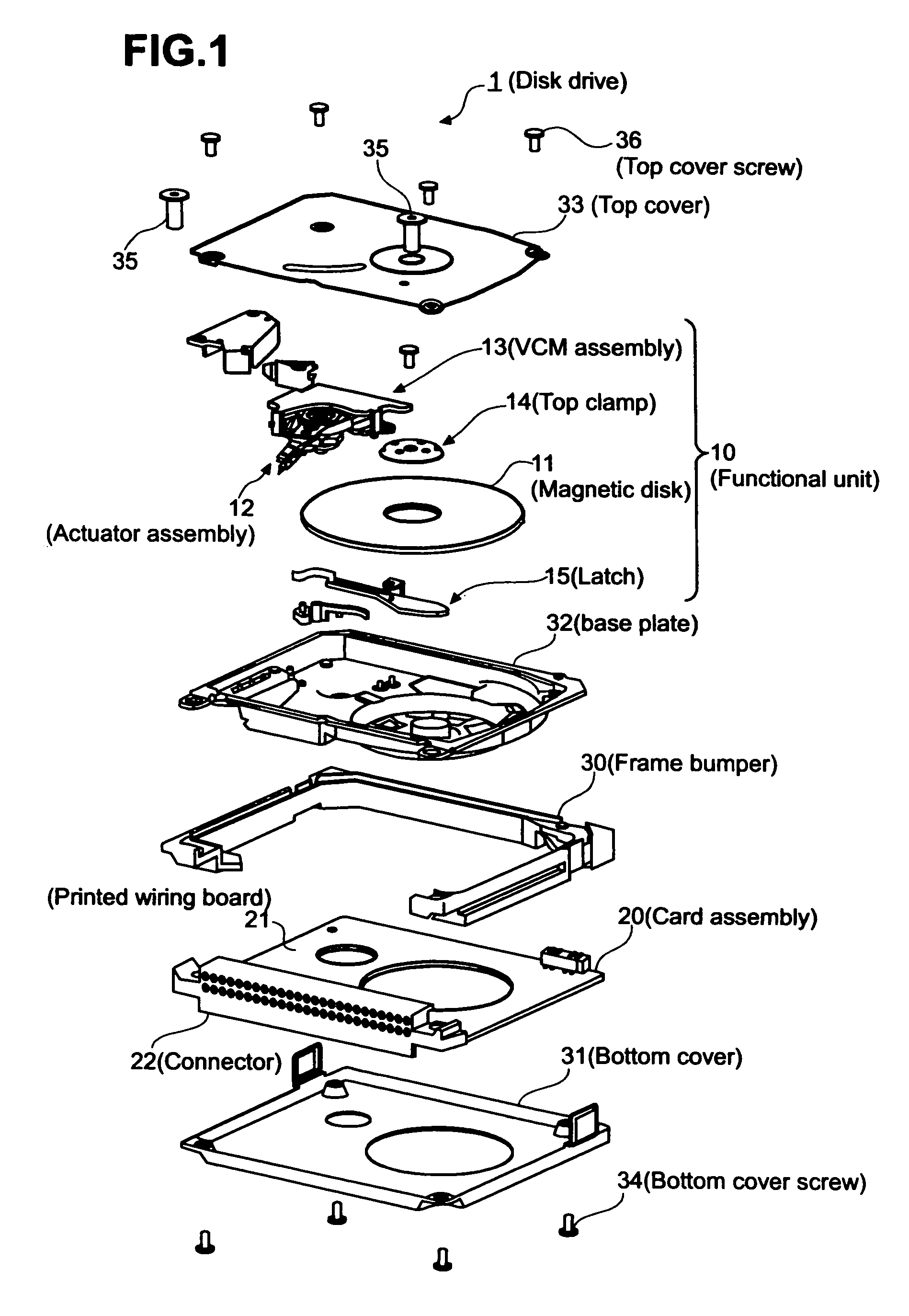
[0029]FIG. 1 is a view of assistance in explaining the assembly structure of a disk drive 1 in a preferred embodiment according to the present invention. The disk drive 1 as a storage medium and a portable precision device conforming to standards of Compact flash type 2, namely, standards for small memory cards, has a functional member 10, i.e., a driving unit (built-in unit), for writing and reading data, and a card assembly 20 forming circuits for controlling the driving of the functional unit 10 and data input / output. The functional unit 10 is held in a case assembly. The card assembly 20 has a connector (interface connector) 22 satisfying functions and construction specified by the form factor of standards of Compact flash type 2.

[0030]The functional unit 10 includes a magnetic disk (disk) 11, i.e., a storage medium for storing data, supported for rotation, an actuator assembly 12 supporting read / write heads for reading and writing data from and to the magnetic disk 11 on its fr...


PUM


Abstract

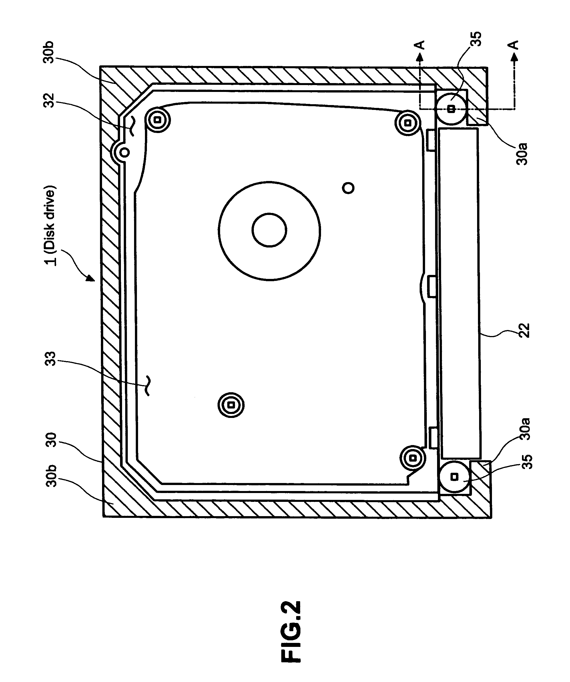
A disk drive having a remarkably improved shock resistance and conforming to a standard form factor is disclosed. A hard disk drive capable of detachably combined with a PC card is formed by assembling separate component parts including a functional unit 10 including a disk 11, a base plate 32 holding the functional unit 10, a frame bumper 30 disposed in a middle part of the assembly and serving as a shock-absorbing member, a card assembly 20 provided with a connector 22 to be connected to the slot of a PC card, and a top cover 33 covering the functional unit 10 held on the base plate 32. The frame bumper 30 receives lateral shocks that act on the side surfaces of the hard disk drive.

Description

PRIORITY APPLICATION[0001]This application claims priority to Japanese Patent Application No. JP2002-316279 (Hitachi Global Storage Technologies Docket No. JP920020172US1), filed on Oct. 30, 2002, and entitled “Disk Drive, Storage Medium and Portable Precision Device”.BACKGROUND OF THE INVENTION[0002]1. Technical Field[0003]The present invention relates to a disk drive used, for example, as a storage medium, and more particularly, to a disk drive having an enhanced shock resistance.[0004]2. Description of the Related Art[0005]Various portable storage mediums have been proposed for storing data in various devices including personal computers (PCs) and digital cameras. Efforts have been made to miniaturize those storage mediums and to increase the capacity of those storage mediums. For example, a new assembly structure of a portable hard disk drive (HDD) conforming to Compact Flash® (SanDisk Corporation), i.e., one of standards for small memory cards, has been proposed.[0006]There has...

Claims


Application Information

Patent Timeline
IPC IPC(8): G11B33/08F16F7/00G06K19/077G11B25/04G11B33/12G11B33/14
CPCG11B25/043G11B33/124G11B33/08
Inventor KIMURA, SHINICHIMATSUDA, HIROSHIMATSUMURA, SATOSHITAMENORI, YUJI
Owner WESTERN DIGITAL TECH INC
Learn More