Ice-making device
a technology of ice-making device and ice-making device, which is applied in the direction of ice production, refrigeration machine, machine using electric/magnetic effect, etc., can solve the problems of large ice-making device and large ice-making devi
- Summary
- Abstract
- Description
- Claims
- Application Information
AI Technical Summary
Benefits of technology
Problems solved by technology
Method used
Image
Examples
first exemplary embodiment
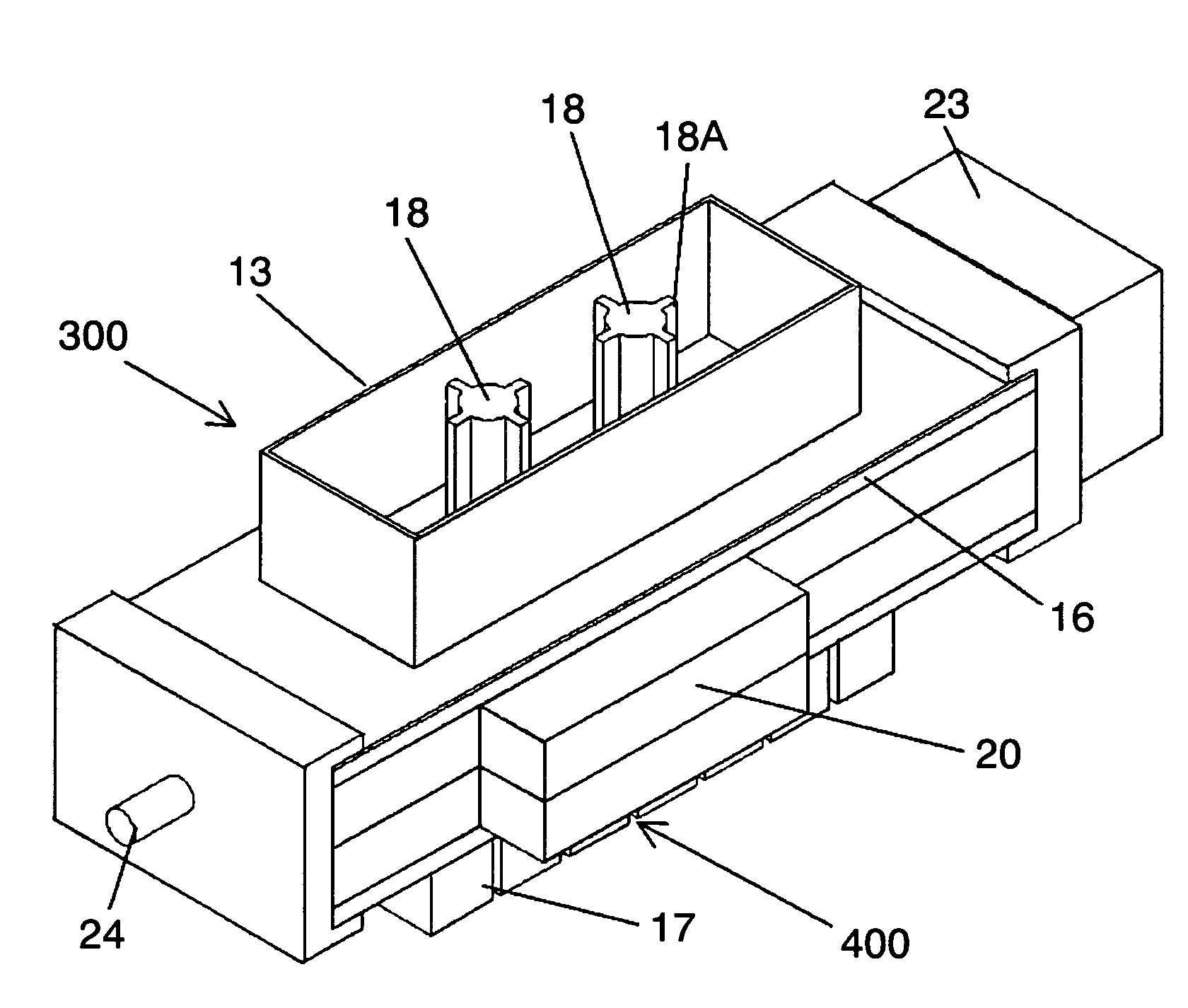
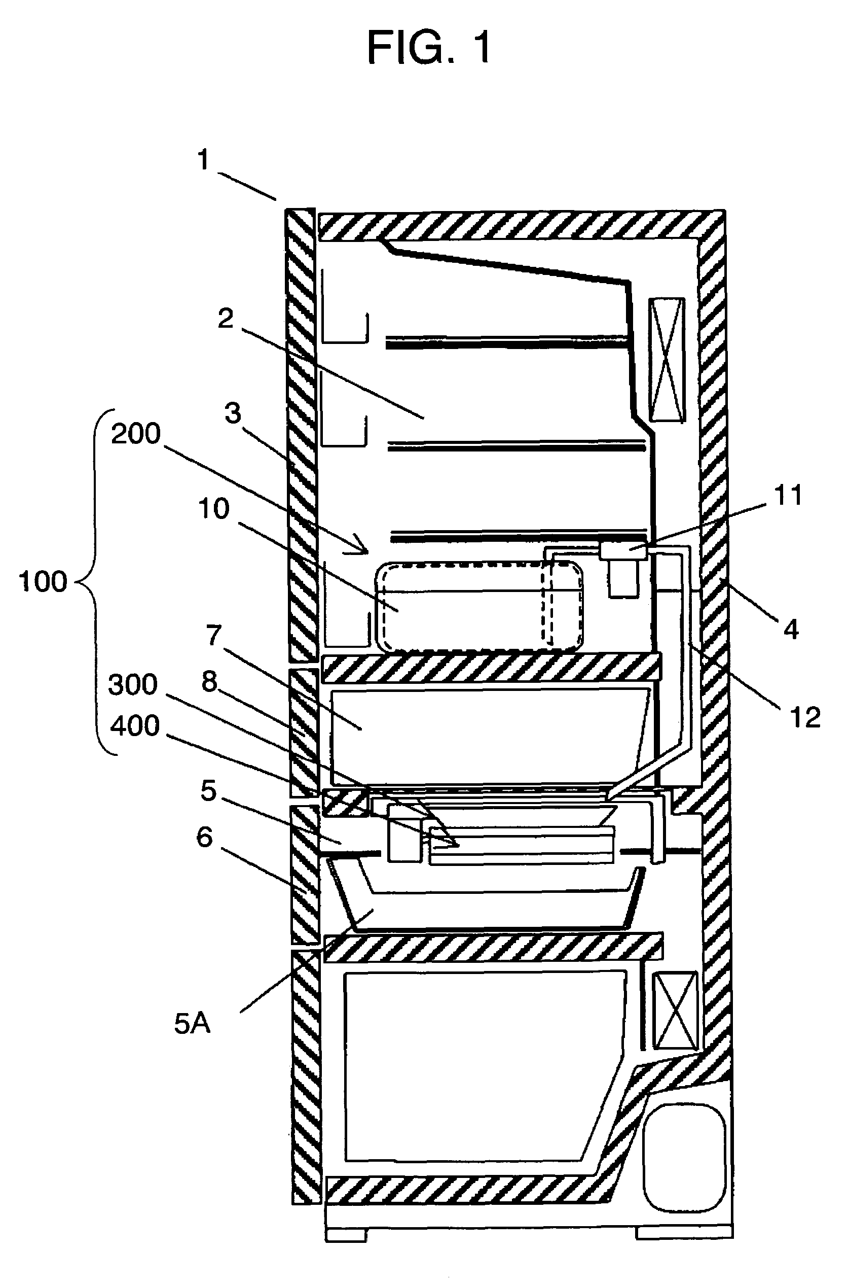
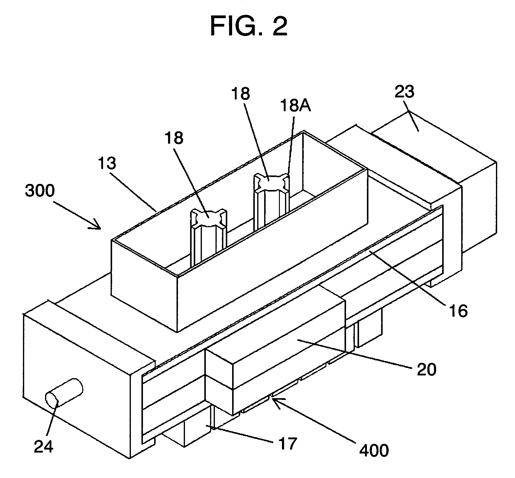
[0057]Referring now to FIG. 1 through FIG. 4, description is provided of the first exemplary embodiment.
[0058]Refrigerator / freezer's main cabinet 1 (hereinafter referred to as main cabinet 1) has a plurality of storage compartments, of which first refrigerator compartment 2 formed in the upper part of it is enclosed and thermally insulated from the external air by door 3 and insulation wall 4. Freezer compartment 5 (hereinafter referred to as ice-making compartment 5) formed under first refrigerator compartment 2 is enclosed and thermally insulated from the external air by insulation wall 4 and door 6. Ice storage box 5A for storing ice cubes is disposed to the lower space of ice-making compartment 5. Second refrigerator compartment 7 located between first refrigerator compartment 2 and ice-making compartment 5 is enclosed and thermally insulated from the external air by insulation wall 4 and door 8. First refrigerator compartment 2 and second refrigerator compartment 7 are connecte...
second exemplary embodiment
[0085]Description is provided of an ice-making device of the second exemplary embodiment with reference to FIG. 5 through FIG. 7.
[0086]Like reference numerals are used to designate like components as those of the first exemplary embodiment, and details of them will be skipped.
[0087]Ice-making device 100 comprises water supply unit 200, ice-making unit 501, and ice-cracking unit 502 for use as ice-cracking means
[0088]Ice-making unit 501 comprises ice-making vessel 503 having an open top and open bottom with side surfaces sloped in a direction to make the top opening larger in area than an area of the bottom opening, for temporarily storing water and making a plank-shaped block of ice, cooling plate 504 fixed to ice-making vessel 503 in a manner that one side surface comes into close contact to and composes a bottom wall of ice-making vessel 503 and the other side surface is in close contact to one surface of Peltier device 14 via heat conduction member 15, and heat sink 17 bonded to ...
third exemplary embodiment
[0102]Description is provided of ice-making device 100 of the third exemplary embodiment with reference to FIG. 1 and FIG. 8 through FIG. 10. Like reference numerals are used to designate like components as those of the first exemplary embodiment, and details of them will be skipped.
[0103]Refrigerator / freezer's main cabinet 1 (hereinafter referred to as main cabinet 1) has a plurality of storage compartments, and first refrigerator compartment 2 formed in the upper part of it is enclosed and thermally insulated from the external air by door 3 and insulation wall 4. Freezer compartment 5 (hereinafter referred to as ice-making compartment 5) formed under first refrigerator compartment 2 is enclosed and thermally insulated from the external air by insulation wall 4 and door 6. Ice storage box 5A for storing ice chips is disposed to the lower space of ice-making compartment 5. Second refrigerator compartment 7 located between first refrigerator compartment 2 and ice-making compartment 5...
PUM
 Abstract
Description
Claims
Application Information
 - R&D
- Intellectual Property
- Life Sciences
- Materials
- Tech Scout
- Unparalleled Data Quality
- Higher Quality Content
- 60% Fewer Hallucinations
Browse by: Latest US Patents, China's latest patents, Technical Efficacy Thesaurus, Application Domain, Technology Topic, Popular Technical Reports.
© 2025 PatSnap. All rights reserved.Legal|Privacy policy|Modern Slavery Act Transparency Statement|Sitemap|About US| Contact US: help@patsnap.com


