
Sound tube tuned multi-driver earpiece

a multi-driver, sound tube technology, applied in the direction of earpiece/earphone manufacture/assembly, electrical transducer, transducer details, etc., can solve the problems of inability to provide high-fidelity performance across all frequencies, cost of armature receivers, typically only found, etc., to achieve the effect of optimizing the audio performance of an earpiece and the resultan

Active Publication Date: 2008-01-08
LOGITECH INT
View PDF8 Cites 61 Cited by
  • Summary
  • Abstract
  • Description
  • Claims
  • Application Information

AI Technical Summary

Benefits of technology

This configuration enhances audio performance by optimizing sound delivery across the entire frequency spectrum, providing better fidelity and mobility for musicians while maintaining a compact design.

Problems solved by technology

Due to the inherent cost of armature receivers, however, they are typically only found in hearing aids and high-end in-ear monitors.
A single armature is capable of accurately reproducing low-frequency audio or high-frequency audio, but incapable of providing high-fidelity performance across all frequencies.
In contrast to the multi-driver approach often used with armature drivers, earpieces utilizing diaphragm drivers are typically limited to a single diaphragm due to the size of the diaphragm assembly.
Unfortunately, as diaphragm-based monitors have significant frequency roll off above 4 kHz, an earpiece with a single diaphragm cannot achieve the desired upper frequency response while still providing an accurate low frequency response.

Method used


Image

  • Sound tube tuned multi-driver earpiece
  • Sound tube tuned multi-driver earpiece
  • Sound tube tuned multi-driver earpiece

Examples


Embodiment Construction

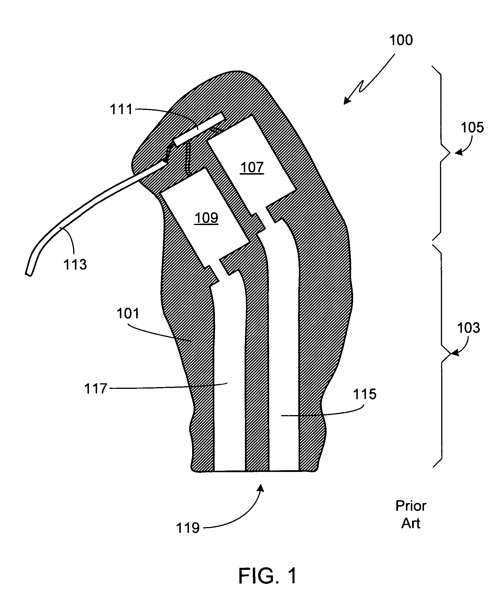
[0022]FIG. 1 is a cross-sectional view of a custom fit earpiece 100 according to the prior art. The term “custom fit” refers to the well known practice in both the in-ear monitor and hearing aid industries of fitting an earpiece to a particular user's ears and, more specifically, to one of the ears of a particular user. In order to custom fit an earpiece, a casting is taken of the user's ear canal and concha. Then an earpiece of the desired type is molded from the casting.

[0023]As shown in FIG. 1, earpiece 100 includes a molded earpiece housing 101, a first section 103 of which is designed to fit within the outer ear canal of the user and a second section 105 of which is designed to fit within the concha portion of the ear. In the illustrated example, earpiece 100 includes a low-frequency driver armature driver 107 and a high-frequency armature driver 109. A circuit 111, such as a passive crossover circuit or an active crossover circuit, provides input to armature drivers 107 and 10...


PUM


Abstract

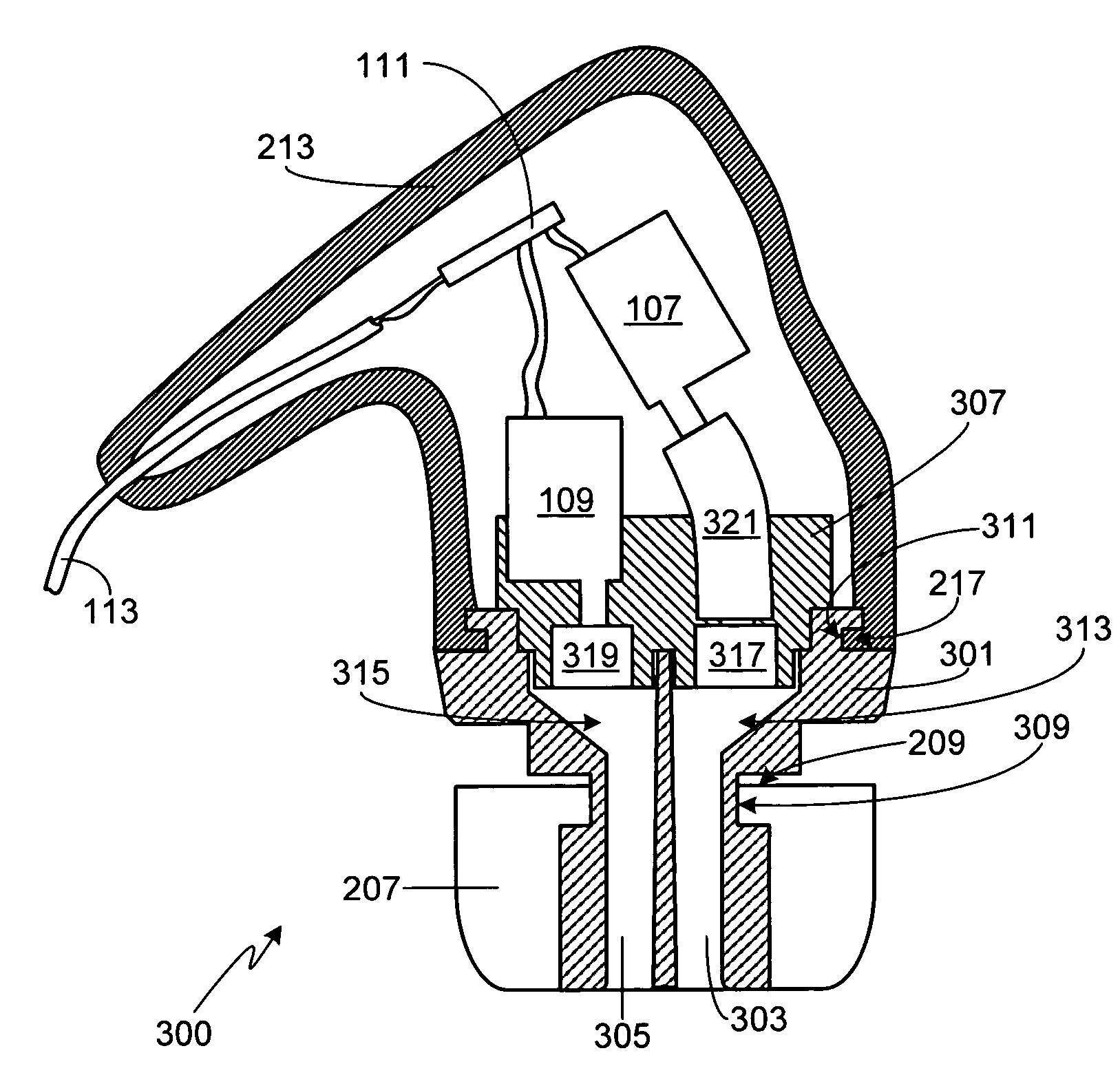
A method of optimizing the audio performance of an earpiece and the resultant device are provided. The disclosed earpiece combines at least two drivers within a single earpiece. If a pair of drivers is used, each driver has a discrete sound delivery tube. If more than two drivers are used, preferably the outputs from the two lower frequency drivers are merged into a single sound delivery tube while the output from the third driver is maintained in a separate, discrete sound tube. To compensate for the inherent phase shift of the earpiece the lengths of the sound delivery tubes, and thus driver offset, are regulated. Further audio performance optimization can be achieved through an iterative process of measuring the performance of the earpiece and making further, minor adjustments to the sound delivery tube lengths. The sound delivery tubes can include transition regions. The earpiece is configured to use removable / replaceable eartips. Acoustic filters can be interposed between one or both driver outputs and the earpiece output.

Description

CROSS-REFERENCES TO RELATED APPLICATIONS[0001]This application is a continuation-in-part of U.S. patent application Ser. No. 11 / 051,865, filed Feb. 4, 2005, which is a continuation-in-part of U.S. patent application Ser. No. 11 / 034,144, filed Jan. 12, 2005 now U.S. Pat. No. 7,194,103, which claims the benefit of U.S. Provisional Patent Application Ser. Nos. 60 / 639,407, filed Dec. 22, 2004, and 60 / 639,173, filed Dec. 22, 2004, all the disclosures of which are incorporated herein by reference for any and all purposes.FIELD OF THE INVENTION[0002]The present invention relates generally to audio monitors and, more particularly, to an in-ear multi-driver earpiece.BACKGROUND OF THE INVENTION[0003]Earpieces, also referred to as in-ear monitors and canal phones, are commonly used to listen to both recorded and live music. A typical recorded music application would involve plugging the earpiece into a music player such as a CD player, flash or hard drive based MP3 player, home stereo, or simi...

Claims


Application Information

Patent Timeline
Patent Type & Authority Patents(United States)
IPC IPC(8): H04R25/00
CPCH04R1/1016H04R1/26H04R1/1058H04R1/225H04R1/2803H04R3/12H04R9/063H04R11/02H04R25/48
Inventor HARVEY, JERRY J.DYER, MEDFORD ALAN
Owner LOGITECH INT
Learn More