
Flow sensor and fire detection system utilizing same

a flow sensor and flow filter technology, applied in the direction of volume/mass flow, dynamic fluid flow effect, measurement devices, etc., can solve the problems of inability to detect the flow rate of water, mechanical sensors can also operate, and the current use of mechanical sensors is difficult to install, etc., to achieve the effect of less cos

Inactive Publication Date: 2008-01-01
GLOBAL FILE
View PDF9 Cites 6 Cited by
  • Summary
  • Abstract
  • Description
  • Claims
  • Application Information

AI Technical Summary

Benefits of technology

[0005]In one aspect of the invention, an improved flow sensor is provided, which does not require a mechanical switch, and which is much less costly than the current mechanical flow sensors. Preferred forms of sensors according to the invention are smaller than the current mechanical flow sensors and can be installed in any orientation, so larger numbers of these sensors can be used to form a system which can provide more information to fire fighters and others than is feasible with the current system.

Problems solved by technology

The mechanical sensors currently used are difficult to install, since they are large, and must be inserted from the top side of the pipe (which is not always accessible) in order to reduce clogging of the moving paddle from sediment in the water.
In addition, the mechanical flow sensors must be installed in the proper direction with respect to the direction of water flow, since the microswitch used to trigger the device can only operate in one direction.
The mechanical sensors can also operate only when there is a full flow of water in the pipe, and cannot detect lower water flow rates which may indicate leaks within the system.
Further, the paddles sometimes break and impede water flow.
In addition, the mechanical sensors used are very costly.

Method used


Image

  • Flow sensor and fire detection system utilizing same
  • Flow sensor and fire detection system utilizing same
  • Flow sensor and fire detection system utilizing same

Examples


Embodiment Construction

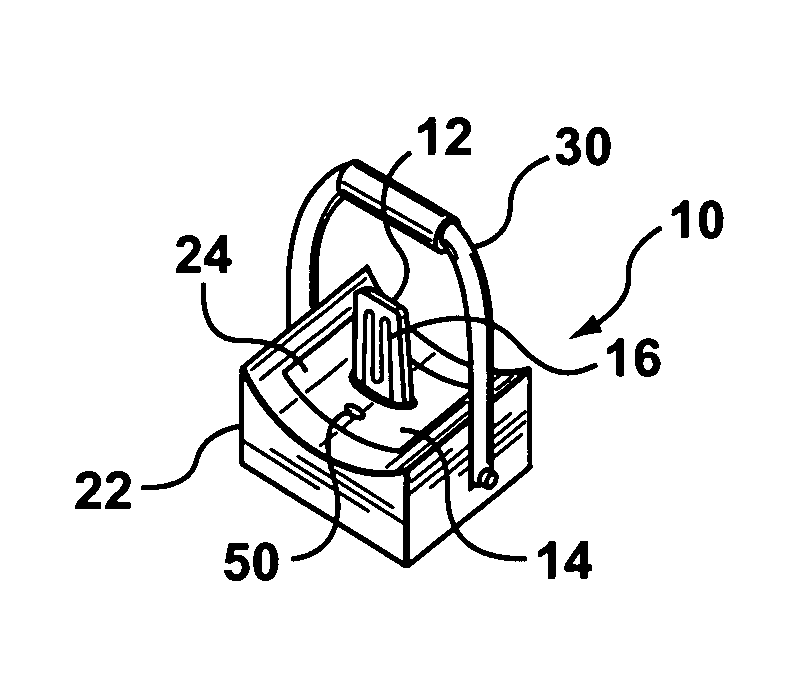
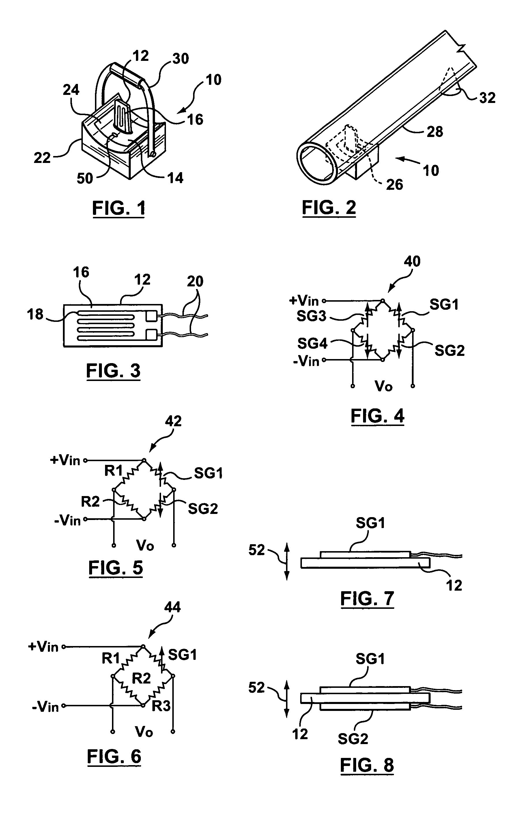
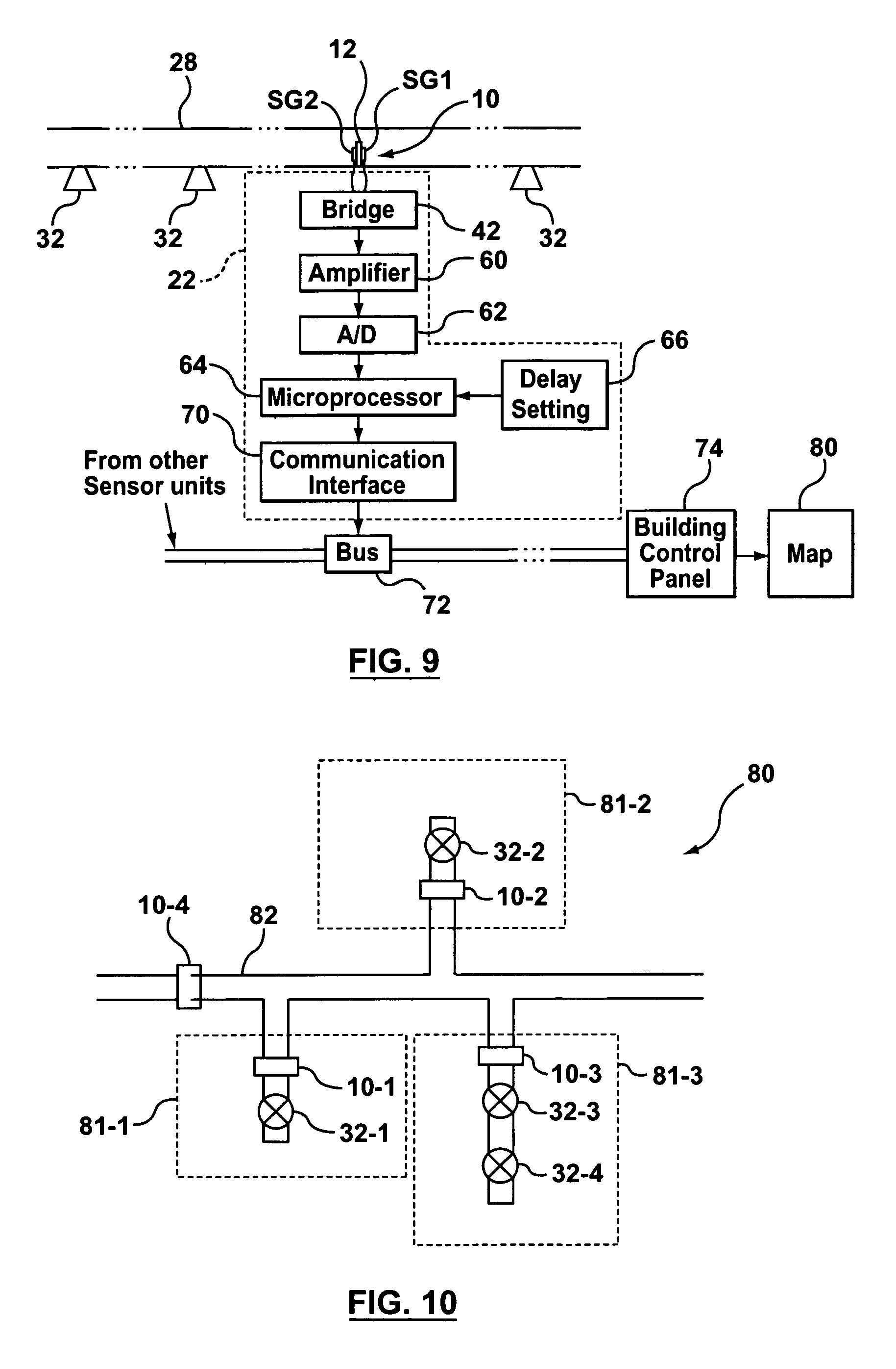
[0031]Reference is first made to FIGS. 1 to 3, which show a flow sensor unit 10. Sensor unit 10 includes a flexible sensing element support 12 mounted on a base 14 and supporting a sensing element 16. In the embodiment being described, the sensing element 16 is a strain gauge. Strain gauges are readily available on the market and are made of a thin wire18 arranged in a zigzag form (as shown in FIG. 3) to form a long electrically conductive strip bonded to a flexible backing (the support 12). When the support 12 is stretched (e.g. when it is bent), the wire 18 is stretched and its electrical resistance increases. The increase in resistance is a measure of the strain (i.e. amount of bending) present in the support 12. Leads 20 are typically connected to each end of the wire 18 which forms the strain gauge, and the leads are brought out to an appropriate amplifying and measuring circuit which detects and measures any change in resistance in the strain gauge.

[0032]In the embodiment of F...


PUM


Abstract

In a fire sprinkler system, flow sensors are used having strain gauges mounted on supports which project into the sprinkler pipes. When water flow occurs, the supports bend, changing the strain gauge resistance and producing a signal which can be analyzed to indicate which sprinkler heads are open. Since there are no mechanical switches, the sensor units are much smaller and cheaper than previously, and provide more information. A strain gauge can also or alternatively be located outside the pipe to detect vibration caused by flowing water. As an alternative to strain gauges, piezo film can be used, with a vibration analyzer to analyze the signal from the film to determine whether water flow is occurring and which sprinkler heads are open. A piezo film can also be placed on the pipe exterior and the signals from the two piezo films can be applied to differential inputs of a differential amplifier, to cancel signals caused by external influences such as pipe vibration. A thermistor can also be used to sense water flow, using temperature changes when the water begins to flow.

Description

CROSS-REFERENCE TO RELATED APPLICATIONS [0001]This application claims priority to U.S. Provisional Application No. 60 / 649,579 filed on Feb. 4, 2005, which is incorporated by reference herein in its entirety.FIELD OF THE INVENTION [0002]This invention relates to fire sprinkler systems, and more particularly to a system including water flow sensors used in fire sprinkler systems.BACKGROUND OF THE INVENTION [0003]Fire sprinkler systems commonly include water flow sensors which are intended to provide some information about the activation of sprinkler heads within the system. The water flow sensors that are currently used throughout the industry are mechanical devices which contain a moving paddle (located within the pipe) and a microswitch. If water begins to flow within the pipe, the water flow displaces the paddle, which activates the microswitch, sending a signal to the building control panel.[0004]The mechanical sensors currently used are difficult to install, since they are large,...

Claims


Application Information

Patent Timeline
Patent Type & Authority Patents(United States)
IPC IPC(8): G01F1/28
CPCG01P13/0033A62C35/605A62C37/08G01F1/28
Inventor SHACHAR, YOSIPANOV, YARON
Owner GLOBAL FILE
Learn More