
Air filter assembly system and method

a technology of air filter and assembly system, which is applied in the direction of filtration separation, other chemical processes, separation processes, etc., can solve the problem of occupying space for such air filter assembly systems

Active Publication Date: 2007-12-25
PARKER INTANGIBLES LLC
View PDF38 Cites 46 Cited by
  • Summary
  • Abstract
  • Description
  • Claims
  • Application Information

AI Technical Summary

Benefits of technology

"The present invention provides an improved air filter assembly system that can be easily located, accessed, and maintained in tight quarters of limited accessibility. The system includes a housing with split halves that can be joined together, an air inlet, a primary filter pack, and a safety filter assembly. The system also includes a filter attachment base assembly and a locking mechanism for securely attaching the housing to the base assembly. The technical effects of the invention include improved air filtration, easy installation, and improved accessibility."

Problems solved by technology

Installation space for such air filter assembly systems, particularly when utilized in mobile applications, such as in trucks and construction equipment or the like, is very limited and access thereto, for maintenance service, such as for the required periodic changing the primary and / or safety filter pack assemblies, is often very tortuous.
However, in this structure, it is the end pan or cover that securely holds the filter in the housing, and is not an integral part of the filter element.

Method used


Image

  • Air filter assembly system and method
  • Air filter assembly system and method
  • Air filter assembly system and method

Examples


Embodiment Construction

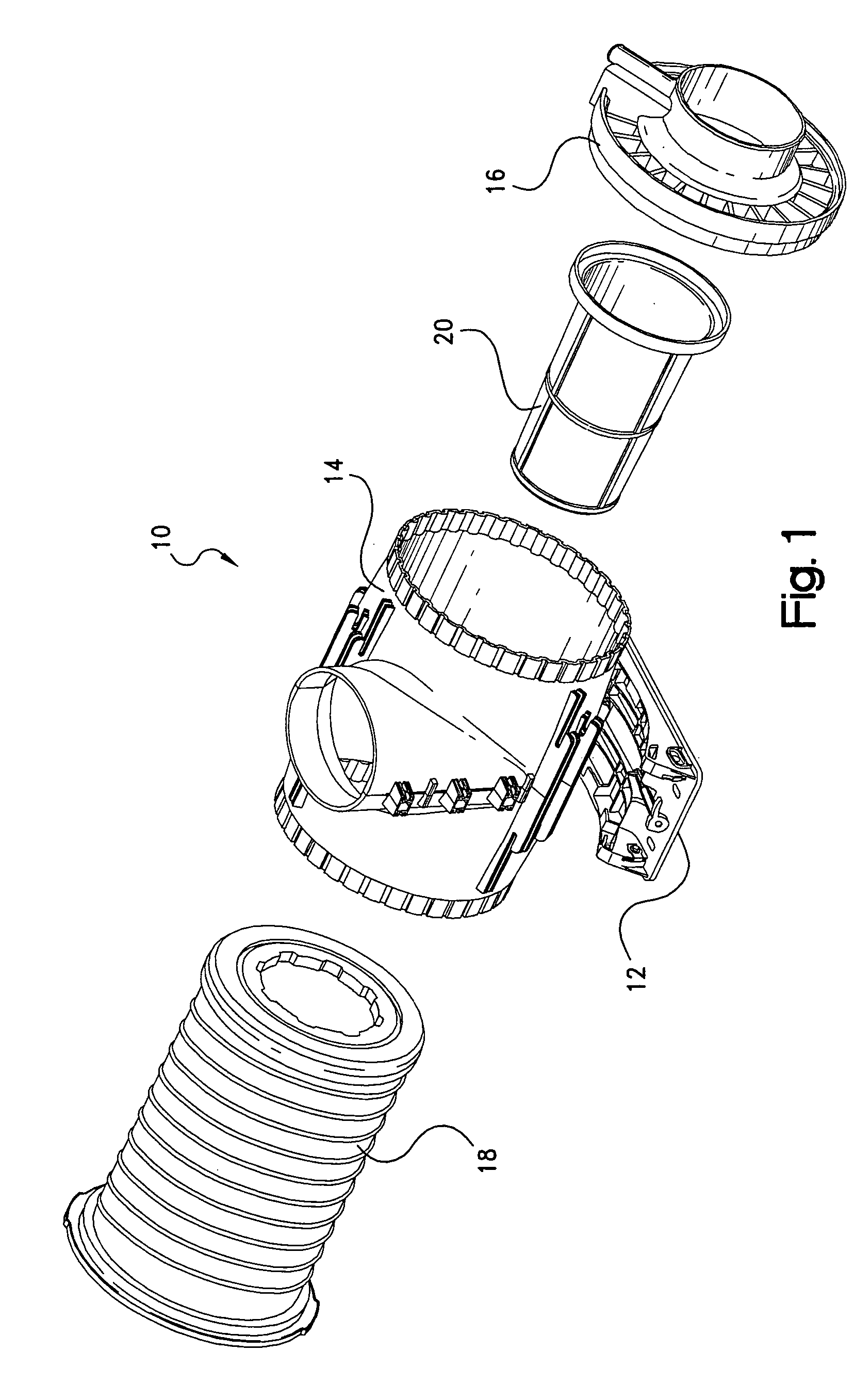
[0085]Referring now to the several drawings, illustrated in FIG. 1 is an exploded, perspective, view of the air filter assembly system, generally indicated at 10, of this invention. Air filter assembly system 10 primarily includes a filter attachment base assembly 12, a filter housing assembly 14, an outlet end 16, a primary filter pack assembly 18 and a safety filter assembly 20, all of which will be discussed in greater detail hereinafter.

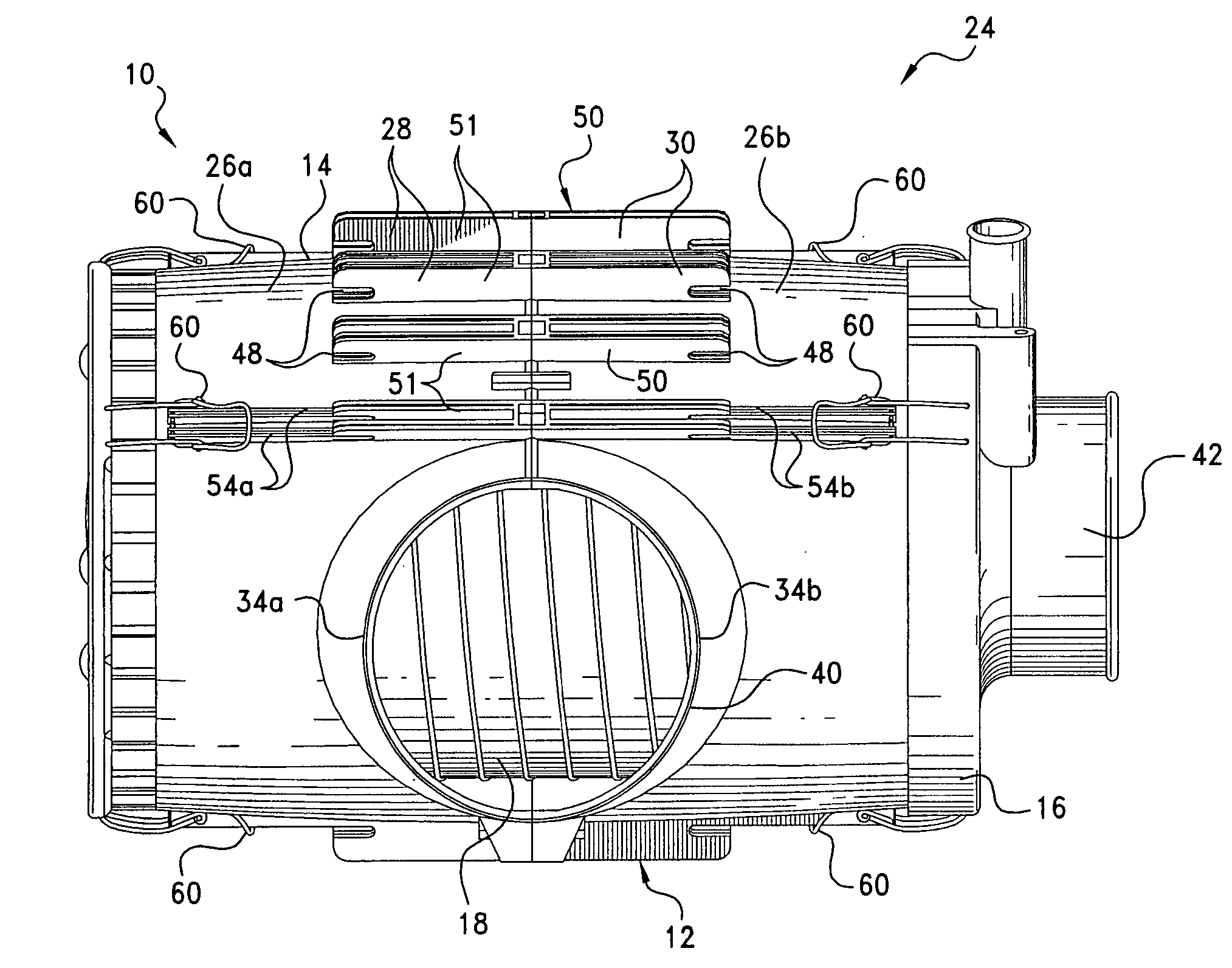
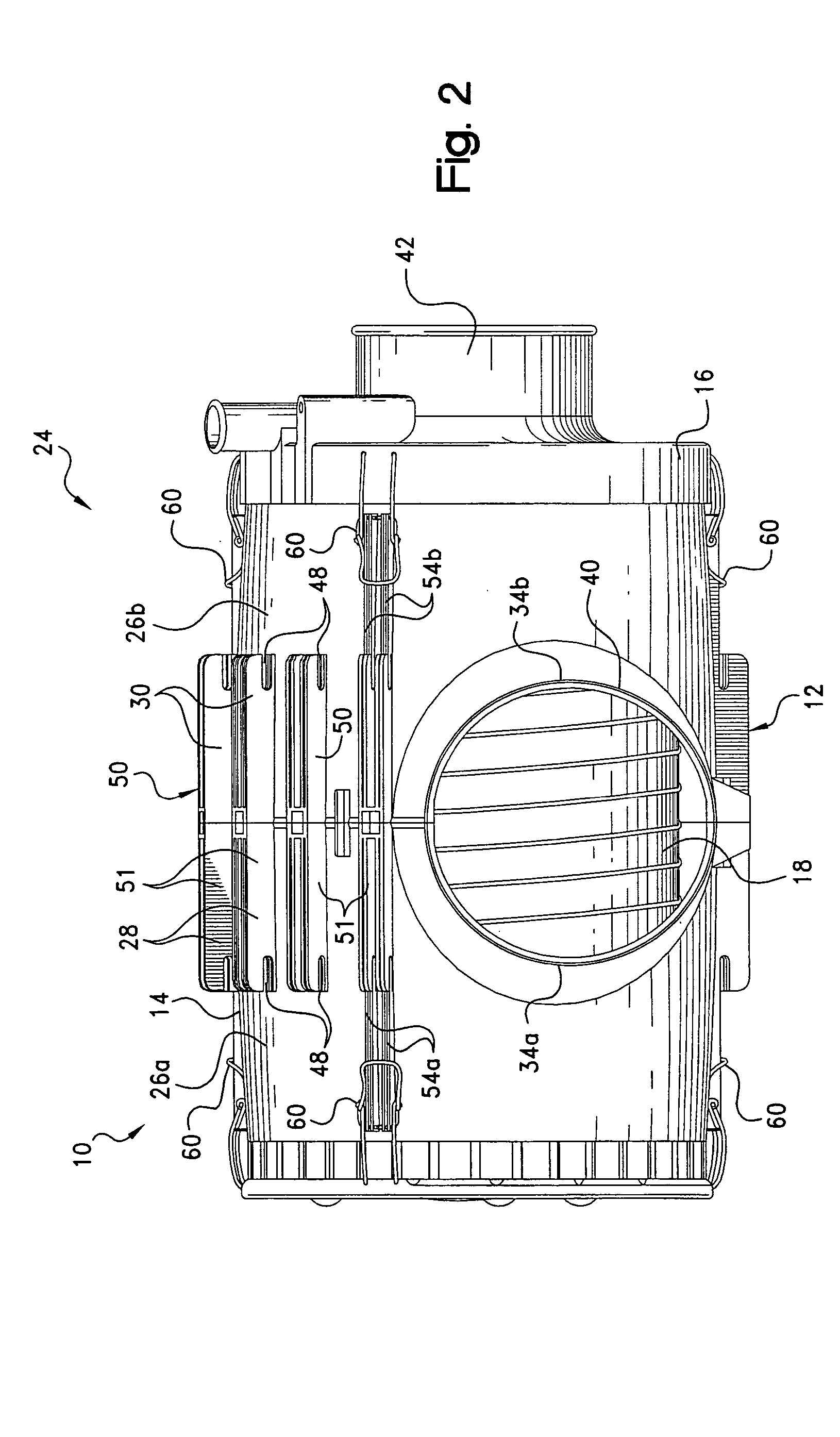
[0086]Illustrated in FIGS. 2-4, is the fully assembled air filter assembly system 10 which can also be defined as the combination of attachment base assembly 12 with an air filter assembly 24, the latter being comprised of filter housing assembly 14, outlet end 16, together with primary and safety filter assemblies 16, 18, respectively. FIG. 2 is a top plan view of air filtration assembly 10, while FIG. 3 is a side view and FIG. 4 is an end view thereof.

[0087]As best seen in FIGS. 5-9, filter housing assembly 14 is basically comprised of two mati...


PUM

PropertyMeasurementUnit
rotationaaaaaaaaaa
rotationaaaaaaaaaa
thicknessaaaaaaaaaa

Abstract

An air filter assembly including abutting, cylindrical housing halves, with toothed outer ends, joined via spaced, T-shaped appendages; a cylindrical air inlet of abutting semi-cylindrical housing inlet portions; a primary filter pack, for slip-fit insertion into either housing half, having an end cap integral with a cylindrical primary filter pack having sealing material on its inner end; a filter outlet end with a toothed peripheral portion, for slip-fit insertion into and angular adjustment relative to either housing end, and a plurality of ribs defining locating surfaces for an air outlet portion, and main and safety filters; the latter having a truncated cone body and an inverted conical portion; and a filter attachment base having curved bed portions, for receiving a housing periphery portion, including spaced support pads and slot portions for angularly adjustably receiving like numbers of T-shaped appendages, with a locking mechanism joining the housing and attachment base.

Description

CROSS-REFERENCE TO RELATED CASES[0001]The present application claims the benefit of the filing date of U.S. patent application Ser. No. 60 / 549,515, filed Mar. 2, 2004, the disclosure of which is fully incorporated herein by reference.FIELD OF THE INVENTION[0002]The present invention pertains to an air filter assembly system and in particular to an air filter assembly which has a housing comprised of two abutting cylindrical housing halves that include toothed outer ends and integral semi-cylindrical air inlet portions; a replaceable, primary filter assembly, having a rigid end cap integral with a cylindrical filter pack; a filter outlet end, with a toothed peripheral portion, for slip-fit insertion and angular adjustment relative to either housing end; and a unique replaceable safety filter seated thereon. A separate filter attachment base, with a curved arcuate segment adapted for receiving a housing periphery portion, includes a plurality of spaced support pads and slot portions f...

Claims


Application Information

Patent Timeline
Patent Type & Authority Patents(United States)
IPC IPC(8): B01D46/00B01D46/24B01D46/52F02M29/06F02M35/02F02M35/024
CPCB01D46/0002B01D46/009B01D46/2411B01D46/4218B01D46/521F02M35/0203B01D46/0005Y10S210/17B01D2265/028B01D2265/05B01D2265/06B01D2271/02F02M29/06F02M35/024Y10S264/48B01D46/00B01D46/24
Inventor HOLMES, LESTER E.JONES, STEVEN R.HAGGARD, CLIFFORD D.
Owner PARKER INTANGIBLES LLC
Learn More