
Lockable mount plate

a technology of mounting plate and lock plate, which is applied in the direction of clamps, metal-working machine components, metal-working apparatus, etc., can solve the problems of unfavorable workpiece positioning, unfavorable workpiece positioning, and difficulty in adjusting the position of the clamp, so as to prevent the movement of the clamp attachment, quick and easy interchange

Inactive Publication Date: 2006-08-29
GLENDO +1
View PDF4 Cites 2 Cited by
  • Summary
  • Abstract
  • Description
  • Claims
  • Application Information

AI Technical Summary

Benefits of technology

[0008]The present invention provides an improved mount that does not suffer from the problems and limitations of the prior art mounts detailed above. The inventive mount provides a universal lockable mount that allows for quick and easy interchange among various mountable attachments yet also enables any one of the attachments to be selectively locked to the mount for a secure mount that generally prevents undesired movement of the attachment. In a preferred embodiment, the locking mechanism includes a flexible plate self-biased into an unlock position that is activated into a locked position by a screw, activated from the top of the mount, that adjustably forces an entrapped pin against the flexible plate.

Problems solved by technology

However, it has been determined that jewelry craftsmen increasingly are utilizing attachments that enable and require precise and fine positioning of the workpiece wherein virtually any movement of the attachment once the desired positioning of the workpiece is achieved is undesired.
While the problems identified in the Glaser Contemporaneous Application primarily dealt with undesired movement of the workpiece, it has been determined that many of these same problems are also associated with undesired movement of the attachment relative to the bench.
Prior art mounts are problematic and subject to several undesirable limitations.
For example, although some prior art mounts may enable a relatively quick interchange of attachments on a single mount, this quick interchange function undesirably enables the attachment to be readily moved relative to the mount, even if this movement is unintended.
Such unintended movement of the attachment relative to the bench is undesirable, particularly during crafting applications that demand extremely precise work within relatively tight spaces on materials that are relatively expensive to replace if mistakes occur.

Method used


Image

  • Lockable mount plate
  • Lockable mount plate

Examples


Embodiment Construction

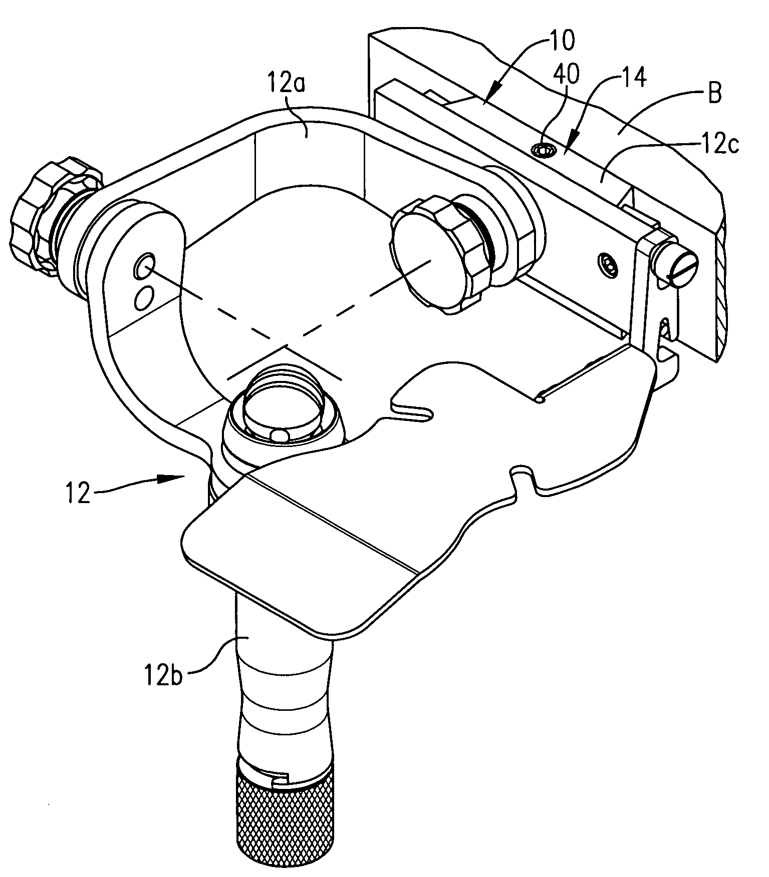
[0019]FIG. 1 illustrates a lockable mount 10 constructed in accordance with the principles of a preferred embodiment of the present invention and shown mounting a jewelry crafting attachment 12 to a workbench B. As further detailed below, the principles of the present invention are not limited to a mount for any particular attachment, nor are they limited to mounting jewelry crafting equipment. Although the principles of the present invention are particularly well suited for mounting jewelry crafting equipment, they equally apply to mounting any type of equipment wherein a secure, selectively lockable mount is desired without compromising any ability for a quick and easy interchange among various attachments. Additionally, the principles of the present invention are not limited to use with the illustrated support B, but could be applied to virtually any type of support wherein it is desirable to mount equipment thereto. The illustrated lockable mount 10 broadly includes a mount plat...


PUM


Abstract

17A lockable mount (10) constructed in accordance with the principles of a preferred embodiment of the present invention and configured for mounting a jewelry crafting attachment (12) to a workbench (B). The illustrated lockable mount (10) broadly includes a mount plate (14) configured to be coupled to the support (B) to receive the attachment (12) and a locking assembly (16) associated with the mount plate (14) for selectively preventing the attachment (12) from moving relative to the mount plate (14). The illustrated mount plate (14) is configured to provide a universal mount wherein several attachments can be quickly and readily interchanged for secure support thereon and comprises a six sided body presenting a generally trapezoidal configuration. The illustrated locking assembly (16) includes a flexible locking plate (36), an entrapped pin (38), and an actuating screw (40). The flexible locking plate (36) is shiftable between a flush position and a locking position. The inventive mount (10) provides a universal lockable mount that allows for quick and easy interchange among various mountable attachments yet also enables any one of the attachments to be selectively locked to the mount (10) for a secure mount that generally prevents undesired movement of the attachment.

Description

BACKGROUND OF INVENTION[0001]1. Field of the Invention[0002]The present invention relates generally to apparatus for mounting equipment to a support and especially for mounting equipment for crafting and repairing jewelry, or for artistic handwork including engraving. More specifically, the present invention concerns a lockable mount that enables the equipment to be normally removably mounted on the support and selectively locked thereto for a secure mount that generally prevents undesired movement of the equipment relative to the support.[0003]2. Discussion of Prior Art[0004]In many applications, a craftsman will desire to mount a piece of equipment to a support, such as a workbench, in order to better utilize the equipment for the selected crafting application. For example, jewelry craftsmen typically mount one of several jewelry crafting attachments to their workbench for performing various jewelry crafting operations therewith. It is often desirable to enable the various attachm...

Claims


Application Information

Patent Timeline
Patent Type & Authority Patents(United States)
IPC IPC(8): B23Q1/25B25B1/22B25B5/08
CPCB25B5/08
Inventor GLASER, DONALD J.TIDWELL, LON C.
Owner GLENDO
Learn More