
Cyclonic separator for mist collectors

a technology of mist collectors and separators, applied in the field of mist collectors and mist collection systems, can solve the problems of need and expense, and achieve the effect of reducing need and expens

Inactive Publication Date: 2007-12-25
FILTRA SYSTEMS COMPANY
View PDF3 Cites 15 Cited by
  • Summary
  • Abstract
  • Description
  • Claims
  • Application Information

AI Technical Summary

Benefits of technology

The separator effectively removes a substantial portion of mist from the air, reducing the workload and maintenance costs of the final cleaning device in mist collection systems, while maintaining low operational expenses and compatibility with existing systems.

Problems solved by technology

As a result, the separator hereof decreases the need for and expense associated with periodic maintenance requirements of the final stage cleaning device in prior mist collection systems.

Method used


Image

  • Cyclonic separator for mist collectors
  • Cyclonic separator for mist collectors
  • Cyclonic separator for mist collectors

Examples


Embodiment Construction

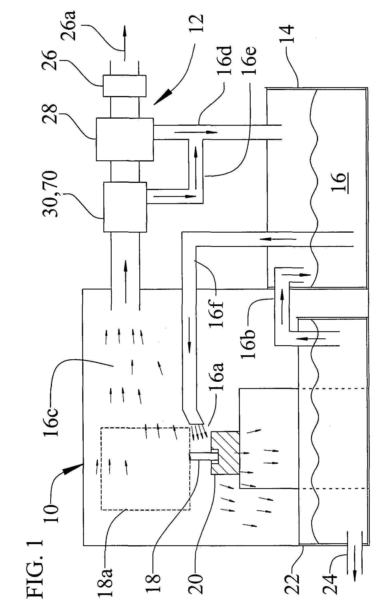
[0034]For purposes of illustration, the present invention is shown diagrammatically in FIG. 1 in connection with a machining center 10 that uses liquid coolant during machining operations, and is provided with a mist collection system 12 for removal of coolant mist from the air surrounding the machining station.

[0035]Briefly, the machining center 10 includes a coolant reservoir 14 from which coolant 16 is conveyed as indicated at 16f and is sprayed as at 16a onto the cutting engagement between a cutting tool 18 (driven by a cutting machine indicated in dashed lines at 18a) and a workpiece 20, and a coolant collection and cleaning station 22 from which chips and other contaminate may be discharged as at 24 and cleaned coolant returned to the reservoir as indicated at 16b.

[0036]The mist collection system 12 includes a fan 26 that draws contaminated air as generally indicated at 16c from the area surrounding the machining station 10, and through a cleaner 28 for removal of the mist th...


PUM

PropertyMeasurementUnit
angleaaaaaaaaaa
angleaaaaaaaaaa
sizeaaaaaaaaaa

Abstract

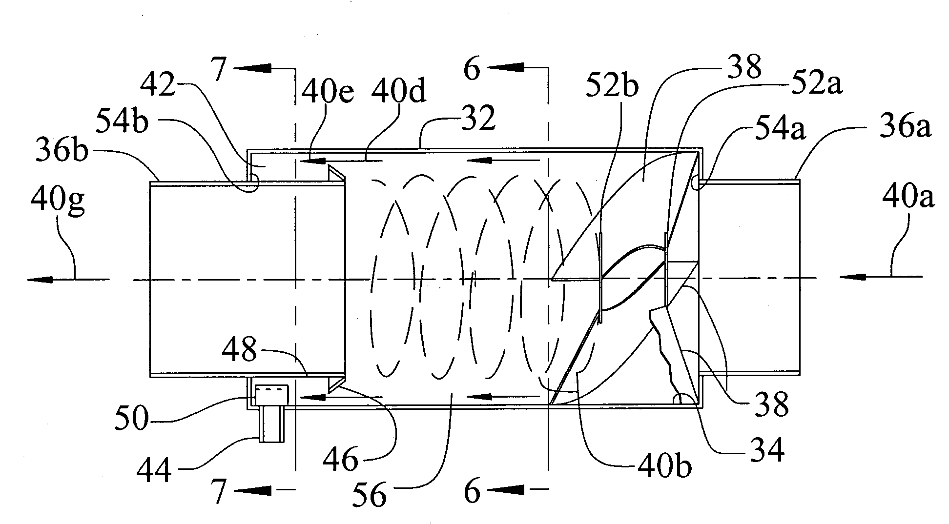
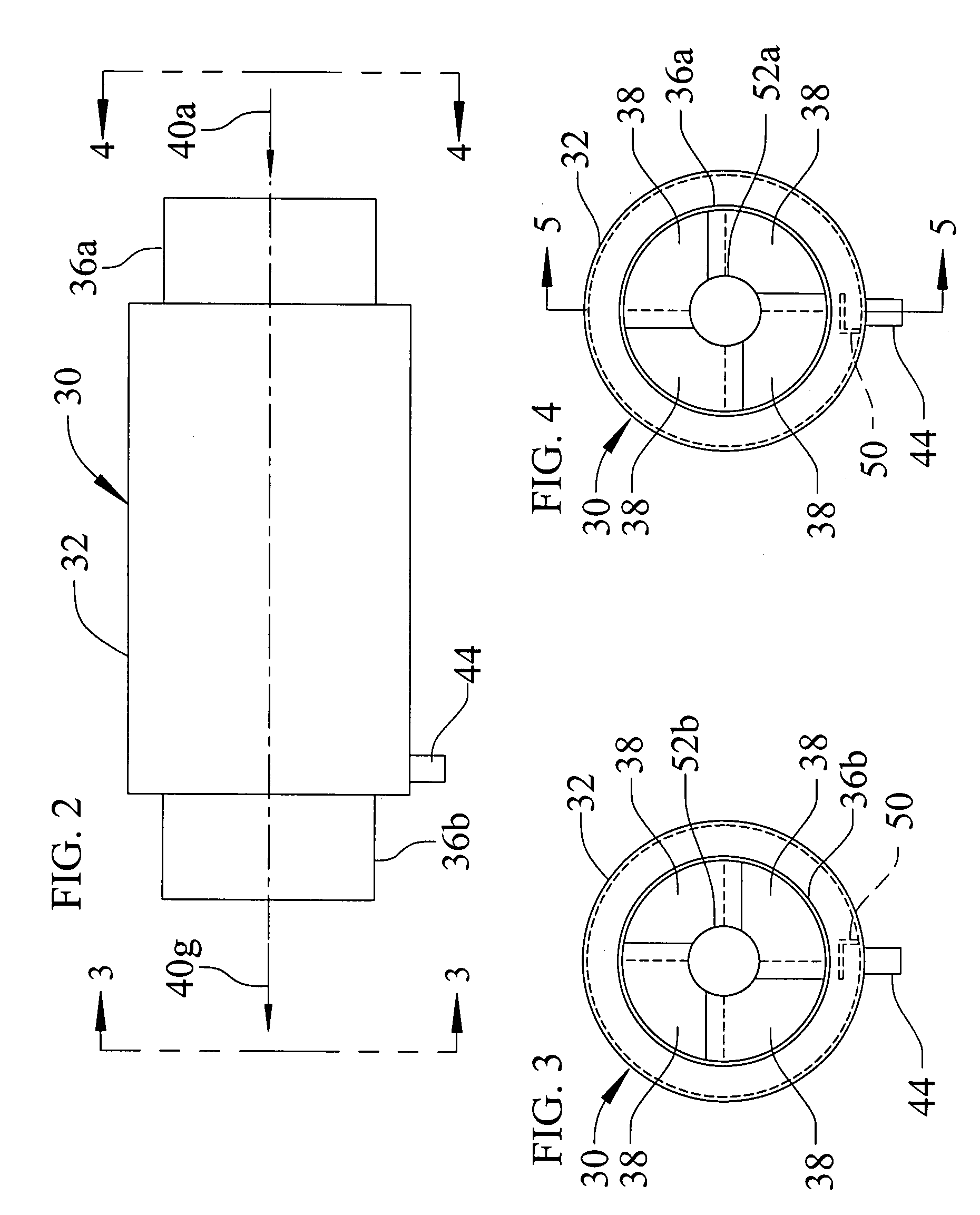
A separator placed in a mist collection system prior to a final air cleaning stage, and is configured to remove a substantial portion of the mist from the air. The separator includes stationary vanes in a cylindrical housing to establish a cyclonic flow therethrough, an annular flow restriction collar to establish a liquid collection area at the downstream end of the housing, a drain for discharge of the liquid from the collection area, and a flow interrupter to direct the swirling liquid into the drain.

Description

CROSS-REFERENCES TO RELATED APPLICATIONS[0001]This application is a continuation-in-part application of U.S. patent application Ser. No. 09 / 930,770, filed Aug. 15, 2001 now abandoned.REFERENCE TO SEQUENCE LISTING TABLE OR COMPUTER PROGRAM LISTING APPENDIX SUBMITTED ON A COMPACT DISC[0002]Not Applicable.STATEMENT REGARDING FEDERALLY SPONSORED RESEARCH OR DEVELOPMENT[0003]Not Applicable.BACKGROUND OF THE INVENTION[0004]1. Field of Invention[0005]The present invention relates generally to mist collectors and mist collection systems of the type suitable to remove oil mist, water vapor, synthetic coolant mist and other mist from the air surrounding commercial machining operations.[0006]More particularly, the invention relates to a separator to remove a substantial portion of such mist prior to the contaminated air reaching a final stage cleaning device in the mist collection system.[0007]2. Description of Prior Art[0008]Mist collectors are commonly used in commercial machining environmen...

Claims


Application Information

Patent Timeline
Patent Type & Authority Patents(United States)
IPC IPC(8): B01D45/12B01D45/16B04C3/00B04C3/06B05B15/12B23Q11/00B23Q11/10
CPCB01D45/16B04C3/00B04C3/06B23Q11/1069B05B15/1285B23Q11/0057B23Q11/10B05B15/1225B05B14/40B05B14/45
Inventor ELLIOTT, MICHAEL R.
Owner FILTRA SYSTEMS COMPANY
Learn More