
Osteoarthritis brace

a technology for osteoarthritis and braces, applied in the field of orthopaedic braces, can solve the problems of prone to modification of osteoarthritis braces,

Active Publication Date: 2007-12-25
DJO
View PDF76 Cites 55 Cited by
  • Summary
  • Abstract
  • Description
  • Claims
  • Application Information

AI Technical Summary

Benefits of technology

The patent describes an osteoarthritis brace and its best mode of use. The brace can be modified and constructed in different ways, as long as it still falls within the scope of the patent. The technical effect of this patent is to provide a flexible and effective tool for managing osteoarthritis.

Problems solved by technology

This osteoarthritis brace is, however, susceptible to modifications and alternate constructions from that discussed above that are fully equivalent.

Method used


Image

  • Osteoarthritis brace
  • Osteoarthritis brace
  • Osteoarthritis brace

Examples


Embodiment Construction

,” one will understand how the features of the preferred embodiments provide advantages, which include flesh containment, distribution of loads over a large portion of the wearer's flesh, elimination of pinch points and enhanced fitting capabilities.

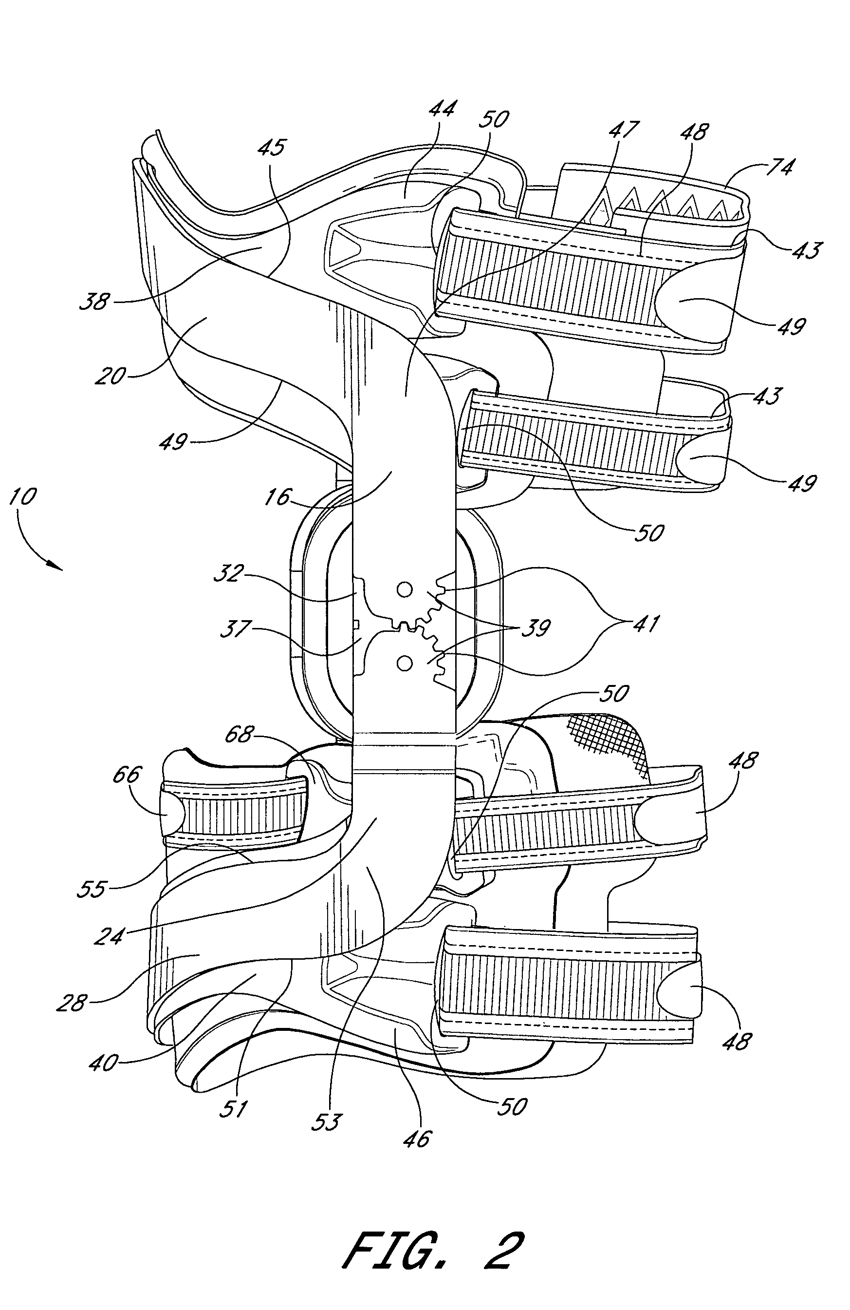
[0009]One embodiment provides an osteoarthritis brace comprising a rigid upper cuff and a rigid lower cuff. At least one hinge pivotably couples the upper cuff to the lower cuff. At least a first semi-rigid cuff abuts a first surface of one of the upper and lower cuffs. The semi-rigid cuff has a larger profile than either of the upper and lower cuffs, such that the semi-rigid cuff is configured to distribute force over a larger area than either of the upper and lower cuffs.

[0010]Another embodiment provides an osteoarthritis brace comprising a rigid upper cuff and a rigid lower cuff. At least one hinge pivotably couples the upper cuff to the lower cuff. At least a first semi-rigid cuff abuts a first surface of one of the upper and lower c...


PUM


Abstract

An osteoarthritis brace having relatively large semi-rigid cuffs for abutting the wearer's thigh and calf. In one embodiment, the semi-rigid cuffs are secured to rigid cuffs of the brace only on one side and in substantially a center of the rigid cuffs. The semi-rigid cuffs bear reaction forces created by a medial / lateral force applied to the wearer's knee by a hinge of the brace. The semi-rigid cuffs provide flesh containment, distribute loads over a large portion of the wearer's flesh, eliminate pinch points and provide enhanced fitting capabilities.

Description

RELATED APPLICATION[0001]This application claims priority to provisional application Ser. No. 60 / 564,563, filed on Apr. 21, 2004, the entire contents of which are hereby expressly incorporated by reference.BACKGROUND OF THE INVENTION[0002]1. Field of the Invention[0003]The present invention relates to orthopedic braces.[0004]2. Description of the Related Art[0005]Osteoarthritis is a degenerative joint disease that causes chronic pain in an affected joint when the joint is statically or dynamically loaded. In an affected knee, osteoarthritis pain is often caused by an unbalanced loading on the medial or lateral compartment of the joint. Such unbalanced loading can generate increased pressure and reduce the clearance space between the condyles of the femur and tibial plateau. Increased pressure between the femoral and tibial surfaces in an affected compartment of the knee joint can cause cartilage degeneration. As cartilage degenerates, the osteoarthritis sufferer generally experience...

Claims


Application Information

Patent Timeline
Patent Type & Authority Patents(United States)
IPC IPC(8): A61F5/00A61F5/01
CPCA61F5/0123A61F2005/0174
Inventor HOFFMEIER, CARLSULLIVAN, JENNIFERMARTIN, JOHNGREGERSEN, COLIN SETH
Owner DJO
Learn More