
Helmet lighting device

a technology for lighting devices and helmets, which is applied in the direction of electric lighting with batteries, lighting support devices, lighting and heating apparatus, etc., can solve the problems of difficult focus or adjustment difficult to adjust the projection of the beam of light therefrom, and often inconvenient use of helmet lights, so as to prevent water damage to the components and accurate light directing

Inactive Publication Date: 2007-12-25
BARNES MARK E
View PDF15 Cites 30 Cited by
  • Summary
  • Abstract
  • Description
  • Claims
  • Application Information

AI Technical Summary

Benefits of technology

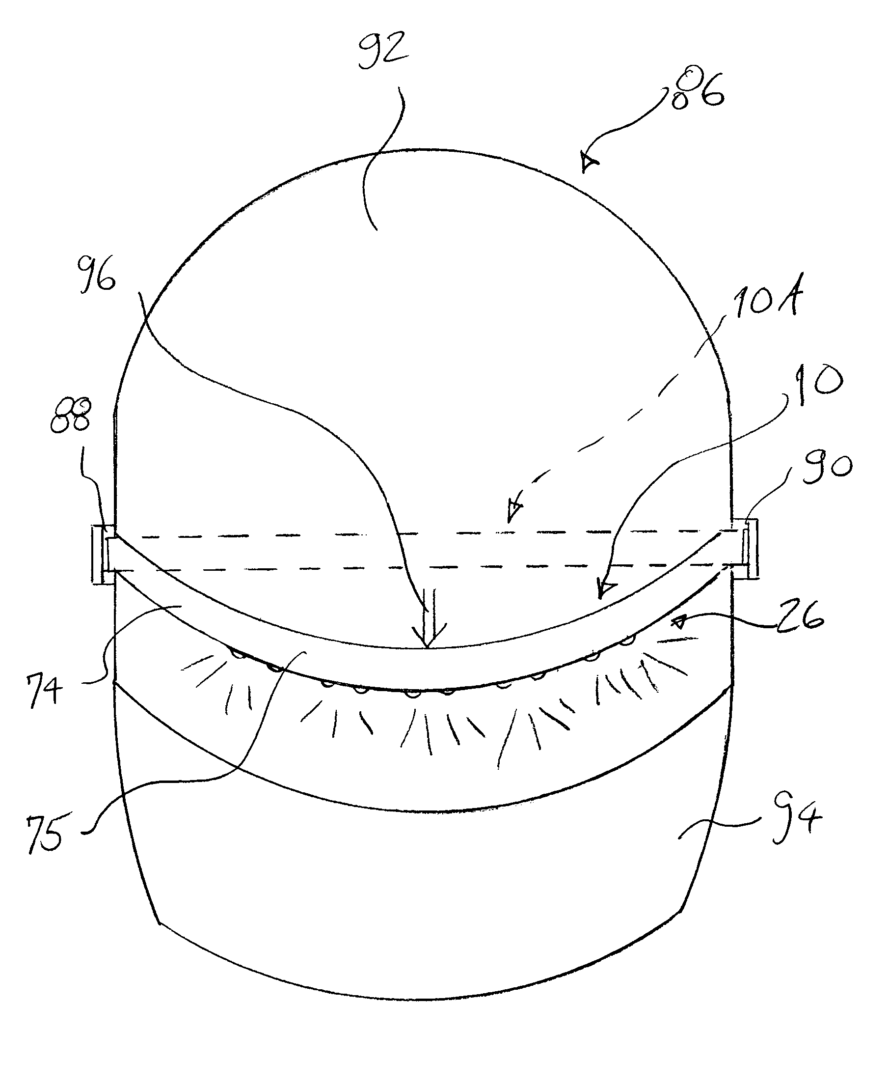
[0013]A sheath extends over the support, the lamp, and at least a portion of the base member to form an enclosure. Such enclosure protects the lamp and any supporting electrical connectors feeding electricity to the lamp within said enclosure. The sheath may be formed of a flexible material which is also non-electrically conductive in this regard. An opening is provided in the sheath for each lamp employed with the base member and support or supports connected to the base member. Each one of the openings allows light to shine from the lamp to the exterior of the sheath. The sheath also includes an exterior surface which frictionally engages the surface of the helmet. For example a rubberized material may be employed to achieve this result. Thus, the sheath, enclosing the base member, support, and lamp, may move between a first position and a second position on the exterior of the helmet. Such movement into these positions facilitates the directing of light of the lamps to a particular place to allow the user of the device of the present invention to identify items and to manipulate such items as is needed in the electrical, plumbing, construction, and other arts.
[0022]Yet another object of the present invention to provide a lighting device for use with a helmet which is lightweight and portable and does not affect the balance of the helmet on the head of the user.

Problems solved by technology

However, helmet mounted lights, in the past, have been difficult to focus or to adjust the projection of the beam of light therefrom.
In addition, helmet lights are often not amenable to being interchangeable with different models or types of helmets, thus being usable with only a single helmet design.

Method used


Image

  • Helmet lighting device
  • Helmet lighting device
  • Helmet lighting device

Examples


Embodiment Construction

[0030]Various aspects of the present invention will evolve from the following detailed description of the preferred embodiments thereof which should be referenced to the prior delineated drawings.

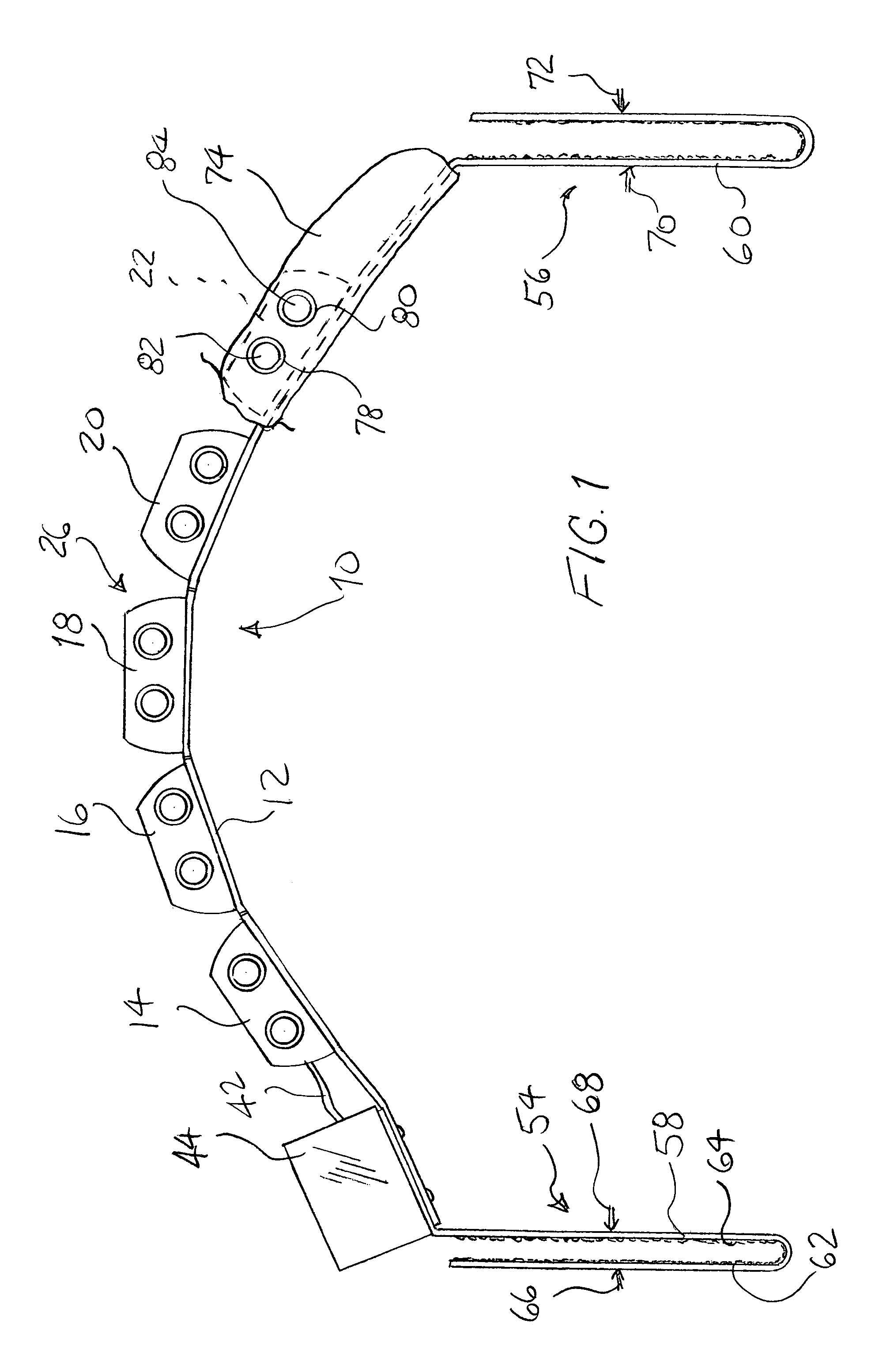
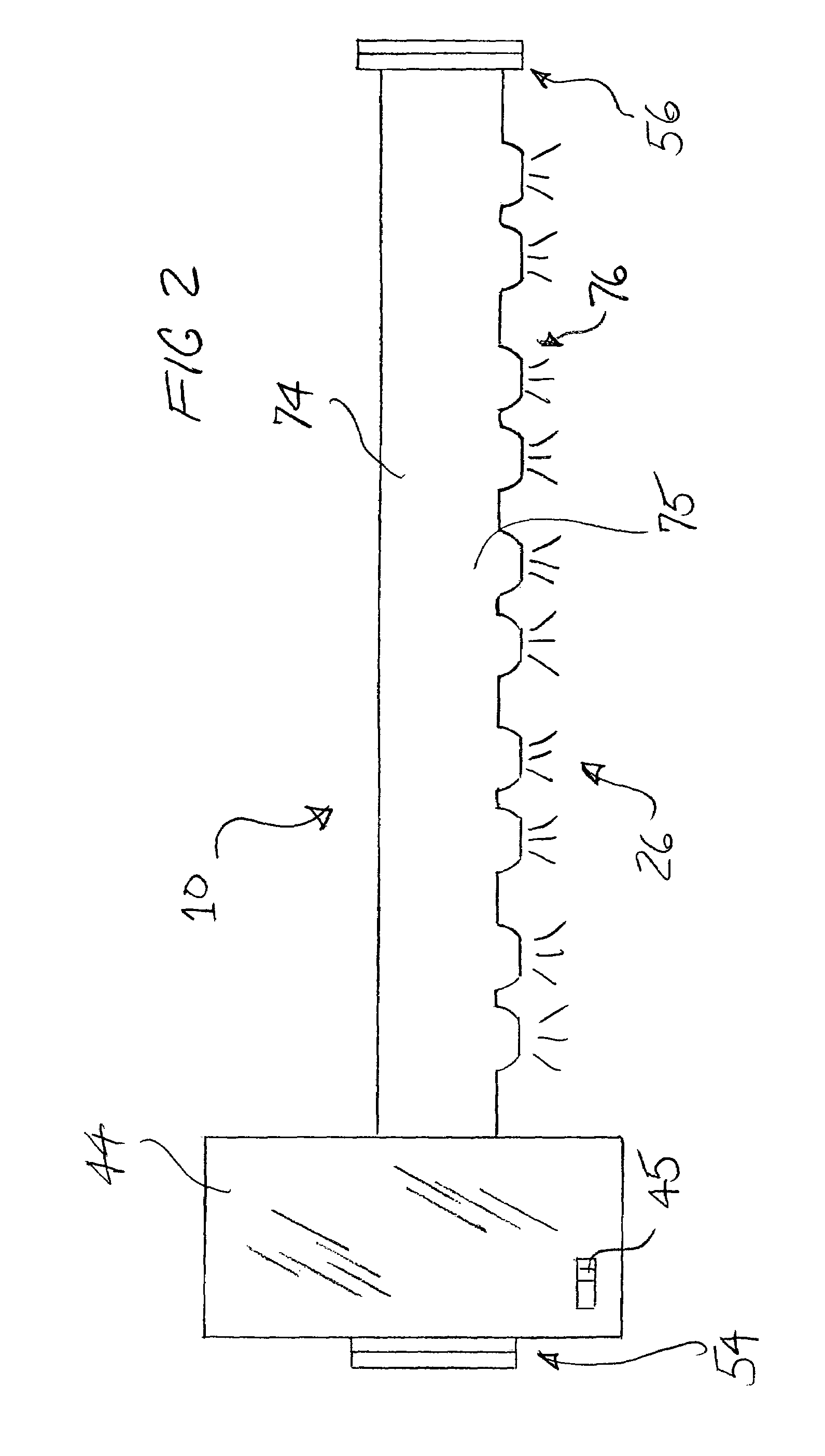
[0031]A preferred embodiment of the invention is shown in the drawings, as a whole, by reference character 10. Lighting device 10, FIG. 1 includes as one of its elements a base member 12 which is shown as generally flattened member extending along a certain 1:0 distance. Base member 12 may further be formed into a metallic member and is preferably bendable. As depicted in FIG. 1, base member 12 has been configured into a generally arcuate configuration by bending base member 12. Thus, base member 12 is generally elongated and extends along a certain distance depending on its use and application.

[0032]Supports 14, 16, 18, 20, and 22 are also included in the present invention. Each support is generally formed into a flat trapezoid-like member. In many cases, supports 14, 16, 18, 20, and 22 ar...


PUM


Abstract

A lighting device for use with a helmet, having a fastening site and a plurality of lamps. A base member is employed and includes at least one support that projects from the same. The support holds at least one lamp. A flexible sheath extends over the support, the lamp, and at least a portion of the base member to form an enclosure. The sheath possesses an opening to allow light to pass from the lamp to the exterior of the sheath. The sheath also includes an outer surface of frictional material to allow the sheath to be frictionally fixed in at least a first and second position at the surface of the helmet. A fastener links the sheath to the helmet.

Description

BACKGROUND OF THE INVENTION[0001]The present invention relates to a novel and useful helmet lighting device.[0002]Headlamps and lamps affixed to helmets are often necessary for persons to operate or work in dark spaces, since a lighting apparatus of this nature frees up both hands of the user. However, helmet mounted lights, in the past, have been difficult to focus or to adjust the projection of the beam of light therefrom. In addition, helmet lights are often not amenable to being interchangeable with different models or types of helmets, thus being usable with only a single helmet design.[0003]In the past, various types of helmet lights have been devised. For example, U.S. Pat. Nos. 5,469,342, 6,619,831, and Des. 375,612 show light strip apparatuses which may be used in various applications.[0004]U.S. Patent Publication 2004 / 0240199 reveals a strip lighting mechanism which illuminates the handle of a container.[0005]U.S. Pat. Nos. 5,667,294, 5,836,673, and 6,575,588 describe stri...

Claims


Application Information

Patent Timeline
Patent Type & Authority Patents(United States)
IPC IPC(8): F21V21/084
CPCA42B3/044
Inventor BARNES, MARK E.
Owner BARNES MARK E
Learn More