
Method and apparatus for filtering gas with a moving granular filter bed

a technology of moving granular filter bed and filter bed, which is applied in the direction of chemistry apparatus and processes, separation processes, dispersed particle separation, etc., can solve the problems of reducing filter efficiency and must be avoided, large irreversible loss of gas momentum, and inability to fluidize, so as to reduce filter efficiency and reduce the effect of filter bed size, high flow velocity and reduced filter efficiency

Inactive Publication Date: 2007-12-18
IOWA STATE UNIV RES FOUND
View PDF10 Cites 12 Cited by
  • Summary
  • Abstract
  • Description
  • Claims
  • Application Information

AI Technical Summary

Benefits of technology

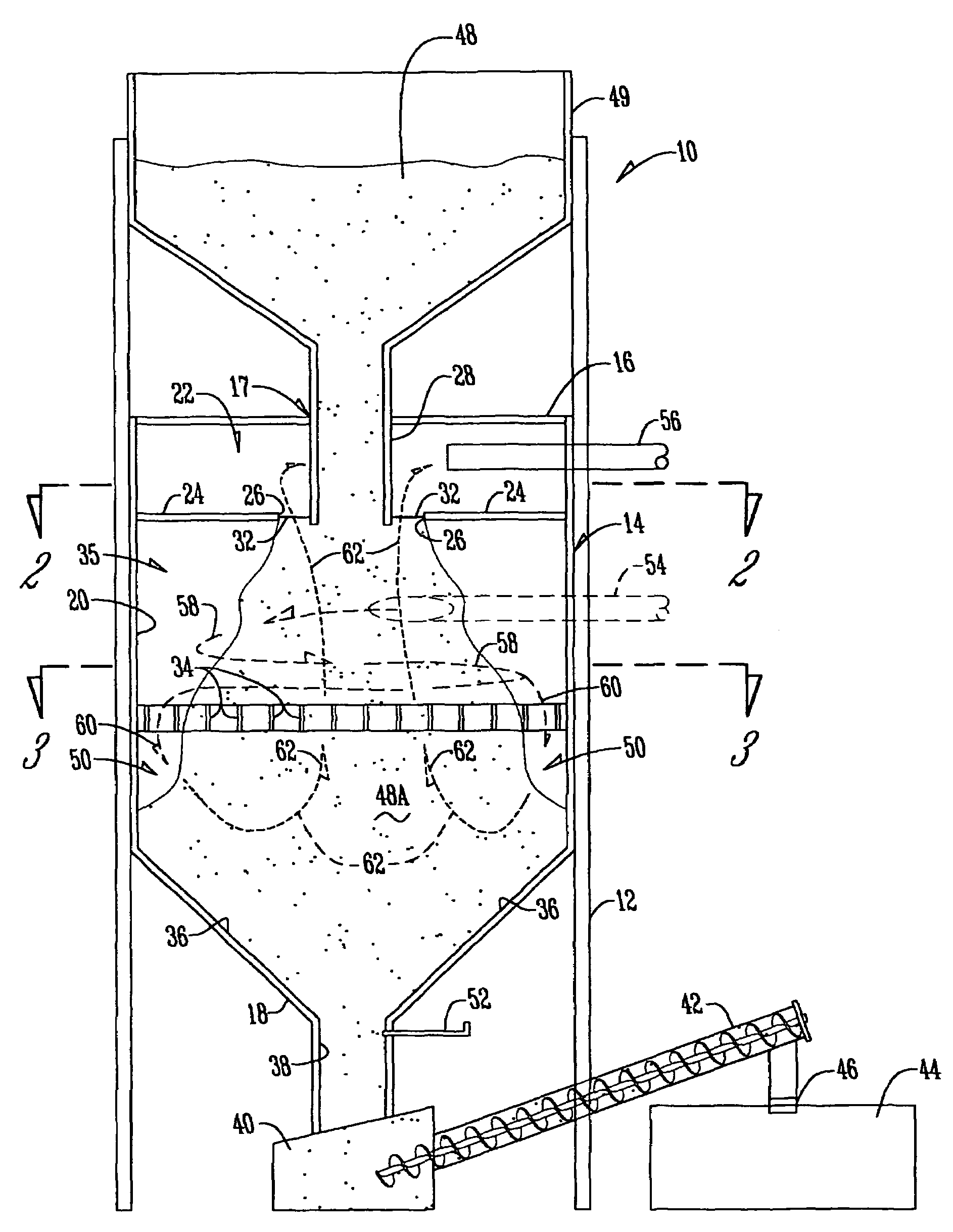
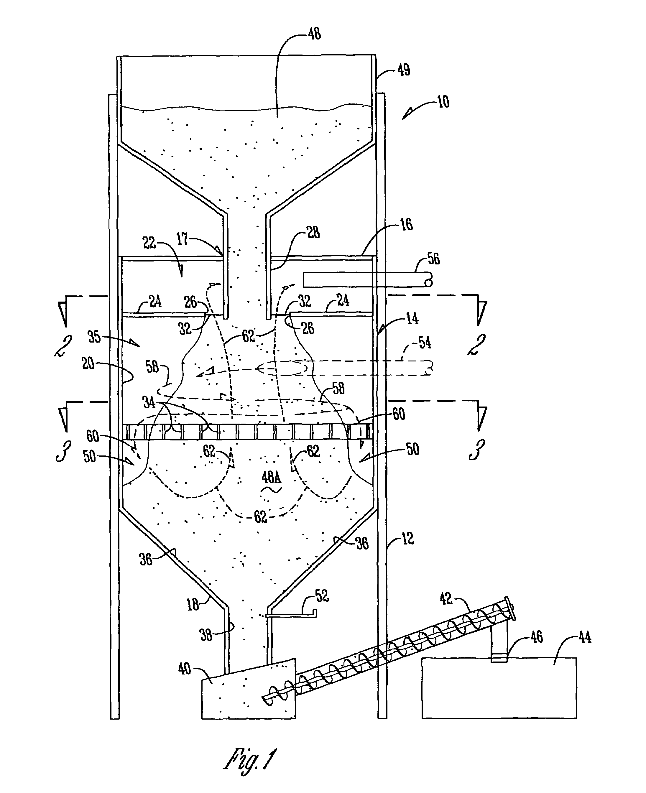
[0011]The design of this invention consists of four main features: a tangential gas inlet, a flow straightening section; a gas disengagement section as shown in FIG. 1, and a diamond shaped insert to enhance filter material flow. The gas enters the filter through a tangential gas inlet, which imparts a cyclonic motion to the gas flow.
[0012]The filter of this invention employs a counterflow of gas and particles, which substantially eliminates the problem of dust carryover in the gas disengagement region. Upward flowing gas can fluidize the granular bed at sufficiently high flow velocities, which greatly reduces filter efficiency and must be avoided. In the instant design, this problem is eliminated by use of a screen at the disengagement interface between the exiting gas and the granular bed. The screen prevents the bed from expanding; thus, it is not able to fluidize. With the screen in place, the gas flow rate through the filter is increased by as much as 67%, which translates to smaller, more economical filters.
[0013]Another advantage of the filter of this invention compared to other moving bed filter designs is the use of a tangential gas inlet, which reduces pressure drop through the filter. Traditional gas inlets inject gas perpendicularly through the side of the filter housing, which results in a large irreversible loss of gas momentum. The tangential inlet converts linear momentum of the gas flow into a cyclonic flow. The preserved momentum of the gas reduces pressure drop by 28-45% compared to a conventional perpendicular gas inlet.
[0014]In an alternate design, a diamond-shaped insert is in the lower region of the housing to change the media flow pattern, which enhances the performance of the filter.

Problems solved by technology

Upward flowing gas can fluidize the granular bed at sufficiently high flow velocities, which greatly reduces filter efficiency and must be avoided.
The screen prevents the bed from expanding; thus, it is not able to fluidize.
Traditional gas inlets inject gas perpendicularly through the side of the filter housing, which results in a large irreversible loss of gas momentum.

Method used


Image

  • Method and apparatus for filtering gas with a moving granular filter bed
  • Method and apparatus for filtering gas with a moving granular filter bed
  • Method and apparatus for filtering gas with a moving granular filter bed

Examples


Embodiment Construction

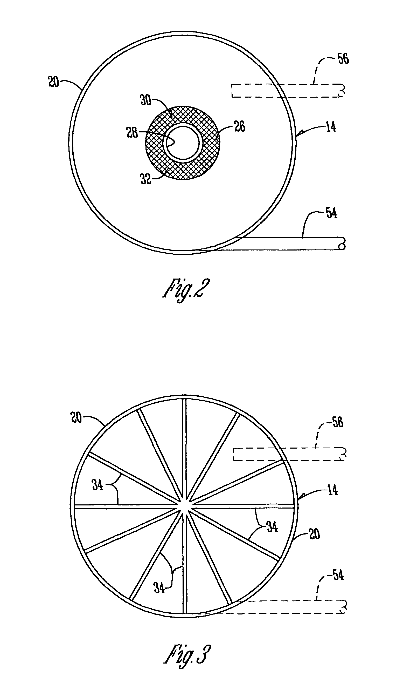
[0019]With reference to FIG. 1 the filter assembly 10 has a conventional supporting frame 12 which supports a filter compartment 14 which is cylindrical in shape. The filter compartment has a top 16 with a center opening 17, a bottom 18, and cylindrical side walls 20. An upper compartment 22 serves as a gas disengagement region and has a bottom partition 24 with a center opening 26 directly below center opening 17 in top 16. A vertically disposed hollow particle inlet conduit 28 extends downwardly through the center opening 17 of top 16 as well as through the opening 26 in bottom partition 24 (FIG. 2). The opening 26 in bottom partition 24 is sufficiently large to provide a circular space 30 around inlet conduit 28 (FIG. 2). A screen mesh 32 extends over space 30 and is connected to bottom partition 24 in any convenient manner.

[0020]A plurality of radially disposed horizontal fins 34 are located in the gas engagement section 35 of filter compartment 14 at a level below the lower end...


PUM

PropertyMeasurementUnit
volumetric flow rateaaaaaaaaaa
velocitiesaaaaaaaaaa

Abstract

A method and apparatus for filtering gas (58) with a moving granular filter bed (48) involves moving a mass of particulate filter material (48) downwardly through a filter compartment (35); tangentially introducing gas into the compartment (54) to move in a cyclonic path downwardly around the moving filter material (48); diverting the cyclonic path (58) to a vertical path (62) to cause the gas to directly interface with the particulate filter material (48); thence causing the gas to move upwardly through the filter material (48) through a screened partition (24, 32) into a static upper compartment (22) of a filter compartment for exodus (56) of the gas which has passed through the particulate filter material (48).

Description

CROSS REFERENCE TO A RELATED APPLICATION[0001]This application is based upon Provisional Patent Application Ser. No. 60 / 314,103 filed Aug. 22, 2001 and Provisional Patent Application Ser. No. 60 / 388,201 filed Jun. 12, 2002.GRANT REFERENCE[0002]Work for this invention was funded in part by a grant from the United States Department of Energy, Contract No. DE-FG26-99FT40588. The government may have certain rights in this invention.BACKGROUND OF THE INVENTION[0003]Counterflow of gas and particles is highly desirable in moving bed granular filters to achieve high dust removal efficiency from contaminated gas streams. In counterflows the dirty entering gas is scrubbed by the dirtiest particles and the clean exiting gas is scrubbed by the cleanest particles. However, moving bed granular filters that utilize counterflow typically have a low gas throughput to prevent bed material from leaving the filter when the minimum fluidization velocity of the granules is exceeded.[0004]A disadvantage o...

Claims


Application Information

Patent Timeline
Patent Type & Authority Patents(United States)
IPC IPC(8): B01D46/32B01D46/34
CPCB01D46/32B01D50/002B01D46/34B01D50/20
Inventor BROWN, ROBERT C.WISTROM, COREYSMEENK, JEROD L.
Owner IOWA STATE UNIV RES FOUND
Learn More