
Femoral head assembly with variable offset

a femoral head and variable offset technology, applied in the field of implantable orthopedic prostheses, can solve the problems of soft tissue surrounding the implant to loosen or lax, the offset decrease greatly affects the success and proper function of the hip implant, and the patient's impingement on the prosthesis,

Inactive Publication Date: 2007-12-11
ZIMMER INC
View PDF22 Cites 22 Cited by
  • Summary
  • Abstract
  • Description
  • Claims
  • Application Information

AI Technical Summary

Benefits of technology

The present invention is about a femoral ball assembly for hip replacement surgery that can be adjusted to different anatomical conditions. The assembly has a smooth spherical head and a variable offset neck that can be adjusted to change the femoral offset. This allows the surgeon to select from a wide range of femoral offsets with a single assembly. The assembly can also have different sized heads and spacers to provide more flexibility in the surgery. The assembly has two parallel axes that form an acute angle with the stem. The technical effects of the invention are that it allows for greater flexibility in hip replacement surgery and reduces the need for a large inventory of differently sized femoral balls.

Problems solved by technology

An unnecessary decrease in offset greatly affects the success and proper function of the hip implant after surgery.
This decrease can result in impingement of the prosthesis for some patients after surgery.
A medial shift can also cause soft tissue surrounding the implant to become loose or lax.
Impingement and soft tissue laxity can further lead to instability of the implant, subluxation, and even dislocation.
As a further disadvantage, when the offset decreases, the abductor muscles utilize a greater force to balance the pelvis.
This increase in force creates a discrepancy that may result in a limp for the patient.
As another consequence, the resultant force across the hip joint also increases, and this increase can lead to greater polyethylene wear between the femoral ball and prosthetic acetabular component.
Further, the costs associated with maintaining and distributing this inventory are very great for a company.
This large inventory, then, is a clear disadvantage.
As another important disadvantage, manufacturers offer the femoral head offsets in fixed, discrete, large increments.
These fixed increments though may not exactly match the anatomical offset that the patient needs.

Method used


Image

  • Femoral head assembly with variable offset
  • Femoral head assembly with variable offset
  • Femoral head assembly with variable offset

Examples


Embodiment Construction

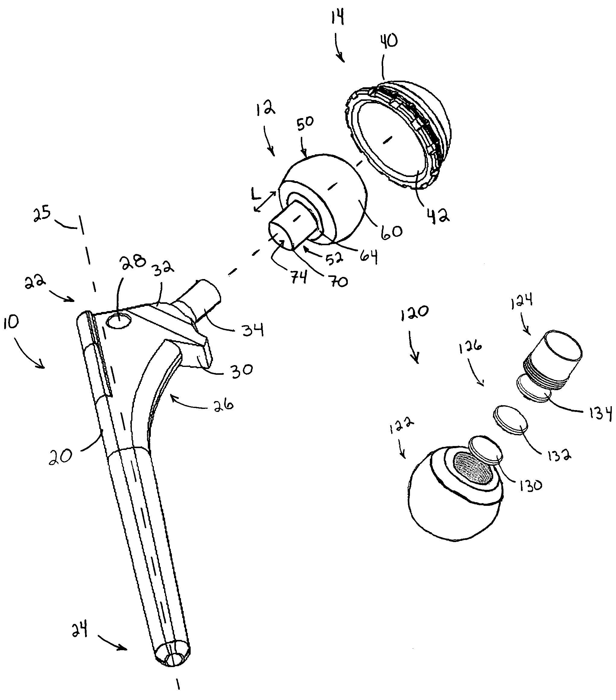
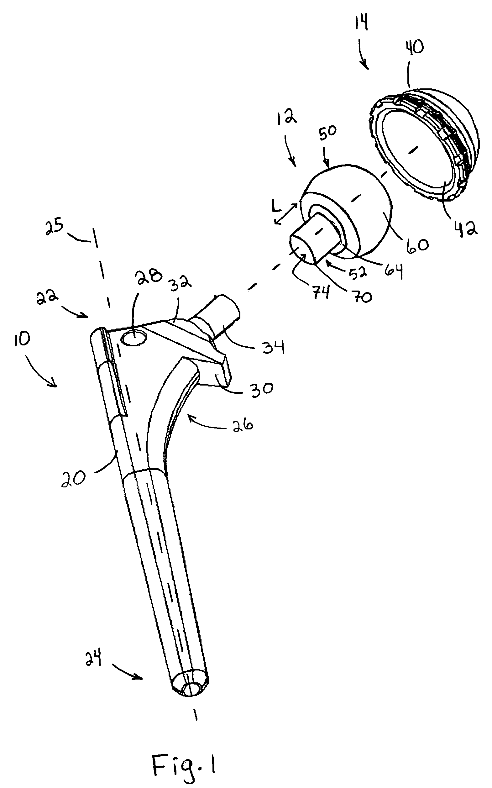
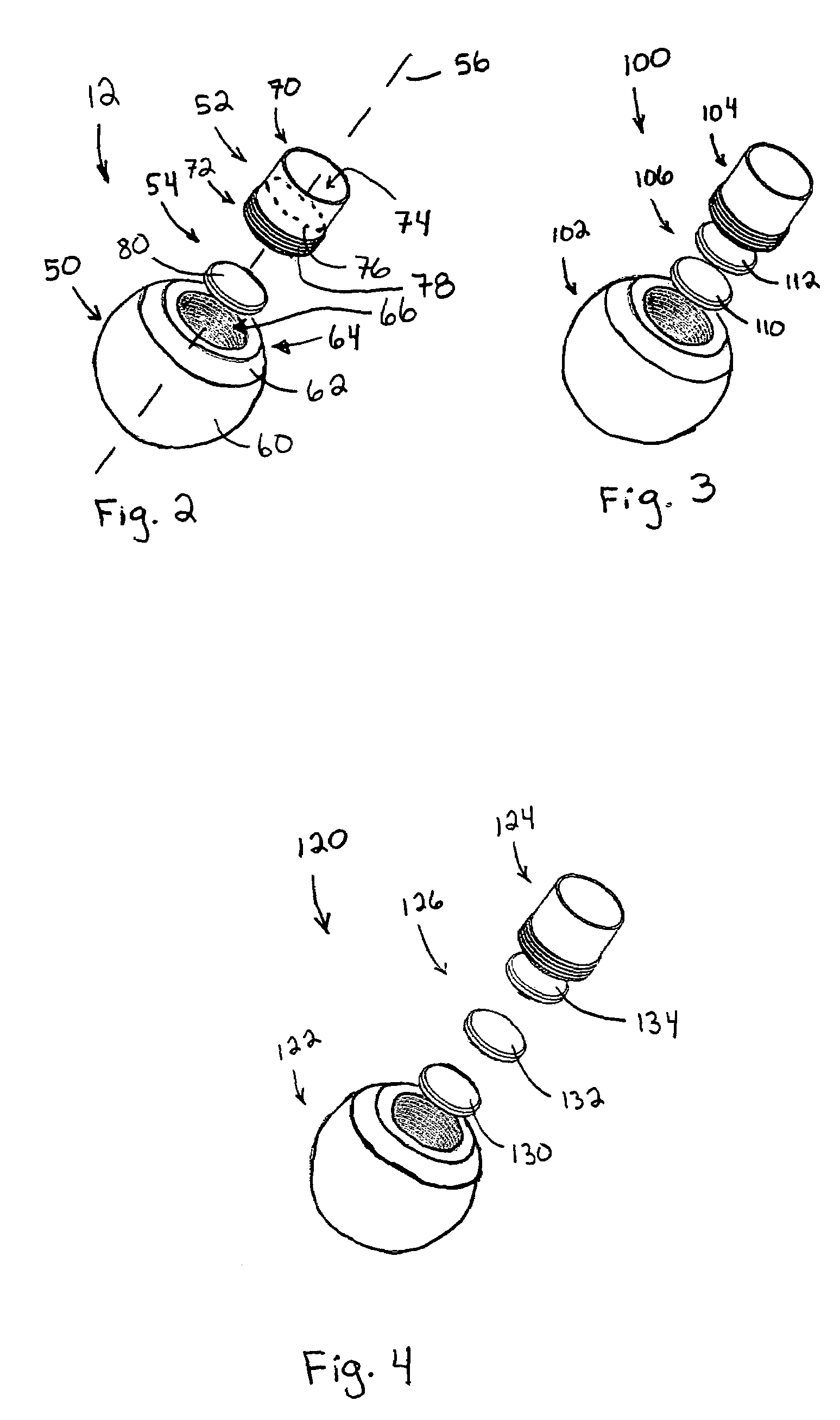
[0027]Looking to FIG. 1, an implantable orthopedic femoral hip stem or implant 10, a proximal femoral head or ball assembly 12 according to the invention, and an acetabular component 14 are shown. These components are connectable together for use in a total hip arthroplasty.

[0028]Stem 10 includes a body 20 that extends from a proximal region 22 to a distal region 24. A longitudinal or long axis 25 extends through the body. The body tapers downwardly and generally has a cylindrical or trapezoidal shape with the distal end being rounded to facilitate insertion into the intramedullary canal of a femur. The proximal region 22 includes a proximal body portion or trochanteral portion 26 having a cylindrical bore 28, a collar 30, and a top surface 32. A neck 34 extends outwardly from the top surface 32. The neck 34 has a tapered body that connects to the femoral ball assembly 12.

[0029]The acetabular component 14 is configured to fit in the acetabulum of a patient and is formed from an oute...


PUM


Abstract

A proximal femoral head assembly having a variable offset that is selectively adjustable to conform to various anatomical conditions encountered during a femoral surgical procedure. The assembly includes a femoral head, a neck removeably connectable to the femoral head, and an adjustment mechanism. The adjustment mechanism provides the neck with a plurality of different femoral offsets with respect to a femoral hip stem.

Description

FIELD OF THE INVENTION[0001]The disclosure generally relates to implantable orthopedic prostheses for total hip arthroplasty and, more particularly, to a proximal femoral head assembly having a variable offset that is selectively adjustable to conform to various anatomical conditions encountered during a femoral surgical procedure.BACKGROUND OF THE INVENTION[0002]During a total hip arthroplasty, a femoral stem is implanted into the intramedullary canal of a femur. After the stem is inserted to the proper depth and orientation, a femoral head or ball is attached to the proximal end of the stem. This head fits into the socket of an acetabular component and provides a joint motion surface for articulation between the femoral prosthesis and acetabulum. A neck or trunion extends between the femoral ball and stem. In many embodiments, this neck generally has a cylindrical configuration with one end connected to the ball and one end connected to the stem.[0003]Several critical features are...

Claims


Application Information

Patent Timeline
Patent Type & Authority Patents(United States)
IPC IPC(8): A61F2/32A61F2/00A61F2/02A61F2/30A61F2/34A61F2/36
CPCA61F2/3609A61F2/30724A61F2310/00179A61F2/32A61F2/34A61F2/36A61F2/3662A61F2/367A61F2/3676A61F2002/30069A61F2002/30092A61F2002/30112A61F2002/30158A61F2002/30224A61F2002/30225A61F2002/30324A61F2002/30332A61F2002/30377A61F2002/30405A61F2002/30444A61F2002/30474A61F2002/30484A61F2002/30497A61F2002/30514A61F2002/30546A61F2002/3055A61F2002/30551A61F2002/30566A61F2002/30574A61F2002/30599A61F2002/30604A61F2002/30616A61F2002/30617A61F2002/30797A61F2002/30886A61F2002/3424A61F2002/3611A61F2002/3625A61F2002/3631A61F2002/365A61F2002/368A61F2210/0014A61F2220/0025A61F2220/0033A61F2220/0041A61F2230/0004A61F2230/0026A61F2230/0069A61F2250/0012A61F2250/0036A61F2250/0063A61F2250/0064A61F2250/0097A61F2310/00017A61F2310/00023A61F2310/00029A61F2/30771A61F2002/30433A61F2002/30495A61F2002/30367A61F2002/342
Inventor SALADINO, JOSEPHNADZADI, MARK E.BURKINSHAW, BRIAN
Owner ZIMMER INC
Learn More