Object lens unit and optical pickup device employing the unit

a technology of optical pickup and object lens, which is applied in the field of optical pickup devices, can solve the problems of difficult to obtain high accuracy of condensing or image formation by a condensing optical system comprising two optical elements, difficulty in aligning various optical elements, and complicated work, etc., to achieve the effect of improving the accuracy of mounting the object lens unit, high condensing characteristics, and low cos

Inactive Publication Date: 2007-11-27
KONICA MINOLTA OPTO
View PDF13 Cites 5 Cited by
  • Summary
  • Abstract
  • Description
  • Claims
  • Application Information

AI Technical Summary

Benefits of technology

[0012]Therefore, the purpose of the present invention is to provide an object lens unit for optical pickup devices that can be manufactured relatively easily and that enable to carry out the relative positioning between the different optical elements and the alignment relative to the holder accurately and efficiently during the manufacturing process. In addition, it is a purpose of the present invention to provide an optical pickup device using the same.
[0014]In the object lens unit of the invention, because accurately machined reference surfaces are provided on the frame and because each optical element is directly in contact with each of the reference surfaces to be fixed, accurate relative positioning between the elements is possible. At the same time, because each optical elements is secured to the frame in an integrated manner, it has a specific accuracy and can be handled as an independent optical component. Furthermore, by having a construction of three components, being the two optical elements and a frame, the shape and structure of each part is simplified and their manufacturing becomes easier. Further, though there are cases in which each reference surface is at an angle to the optical axis, a desired precise tilt angle can be ensured by this reference surface.
[0016]The object lens unit can be handled as an independently integrally shaped optical component even though it has high condensing characteristics due to two optical elements. Therefore, since the relative positions of the different optical elements inside the object lens unit have been adjusted at a high degree of accuracy, in the above fixing means, there is no need to give consideration for the accuracy of the optical characteristics of each optical element inside the object lens unit, and it is sufficient if it can merely improve the accuracy of mounting the object lens unit to the holder. In the optical pickup device of the present invention, since an object lens unit of the above type is incorporated, it is possible to obtain an inexpensive unit at a high accuracy.

Problems solved by technology

However, in the technologies disclosed in Patent Documents 1 and 2, there still remain the problems of alignment of various optical elements that are the constituent elements of the optical system in the manufacturing of condensing optical system for optical pickups.
However, in the above technologies, the work becomes complicated because the work of relative positioning between the different optical elements and the work of their alignment relative to the holder are incorporated in the assembly process of the optical pickup device, whereby it is difficult to obtain high accuracy of condensing or image formation by a condensing optical system comprising two optical elements.

Method used


Image

  • Object lens unit and optical pickup device employing the unit
  • Object lens unit and optical pickup device employing the unit
  • Object lens unit and optical pickup device employing the unit

Examples


Embodiment Construction

[0024]Preferred embodiments of the invention to overcome the above problems will now be explained.

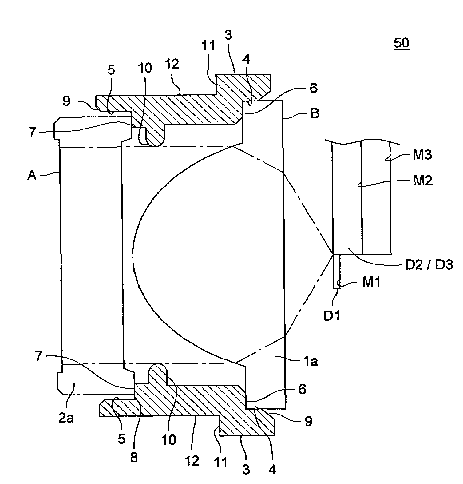
[0025]Further, as another embodiment of the present invention, in an object lens unit, the frame is provided with the first and the second fitting portions in which first and the second optical elements are respectively fitted and that is used to determine the relative positions between the optical elements in a direction perpendicular to the optical axis. In this case, because the relative position is determined between the optical elements concerning the direction perpendicular to the optical axis by the first and the second fitting portions, it is possible to adjust the optical performance characteristics to a still higher degree of accuracy of the optical unit combining the two optical elements.

[0026]In order to solve the above problem, another object lens unit of the optical pickup according to the present invention comprises a first optical element placed facing the optical inform...


PUM


Abstract

An object lens unit for an optical pickup comprising: a first optical element positioned facing an optical information recording medium; a second optical element positioned on a light source side of the first optical element; and a frame which has a first reference surface in contact with the first optical element to position the first optical element in an optical axis direction and a second reference surface in contact with the second optical element to position the second optical element in the optical axis direction so that the first optical element and the second optical element are fixed to be integrated with the frame, wherein the first optical element, the second optical element and the frame are attached, as a single optical component, to another member.

Description

[0001]This application is based on Japanese Patent Application No. 2004-270233 filed on Sep. 16, 2004 in Japanese Patent Office, the entire content of which is hereby incorporated by reference.BACKGROUND OF THE INVENTION[0002]The present invention relates to optical pickup devices for recording and reproducing optical information recording media, and to an object lens unit used in such optical pickup devices.[0003]In recent years, with the practical application of short wavelength red semiconductor lasers, the Digital Versatile Disk (DVD) which is a high density optical disk having a large memory capacity and being of about the same size as a CD (Compact Disk), which is a conventional optical disk (also called an optical information recording medium) has been developed and commercialized.[0004]Following this, optical pickup devices have been developed that are compatible with several types of optical information recording media (specifically, CDs and DVDs). As a pickup of this type,...

Claims


Application Information

Patent Timeline
Patent Type & Authority Patents(United States)
IPC IPC(8): G02B7/02
CPCG02B13/00G11B7/1275G11B7/1374G11B7/13925G11B7/1353G11B2007/0006
Inventor YAMAMOTO, SHOGOATARASHI, YUICHIWADA, KAZUHIROSHIMIZU, TSUTOMU
Owner KONICA MINOLTA OPTO
Why Eureka
Try Eureka