
Ejection control device, liquid-ejecting apparatus, ejection control method, recording medium, and program

a technology of liquid ejection and control device, which is applied in the direction of visual presentation using printer, digital output to print units, instruments, etc., can solve the problems of nozzles not being able to properly eject droplets and problematic line heads

Inactive Publication Date: 2007-11-20
SONY CORP
View PDF9 Cites 2 Cited by
  • Summary
  • Abstract
  • Description
  • Claims
  • Application Information

AI Technical Summary

Benefits of technology

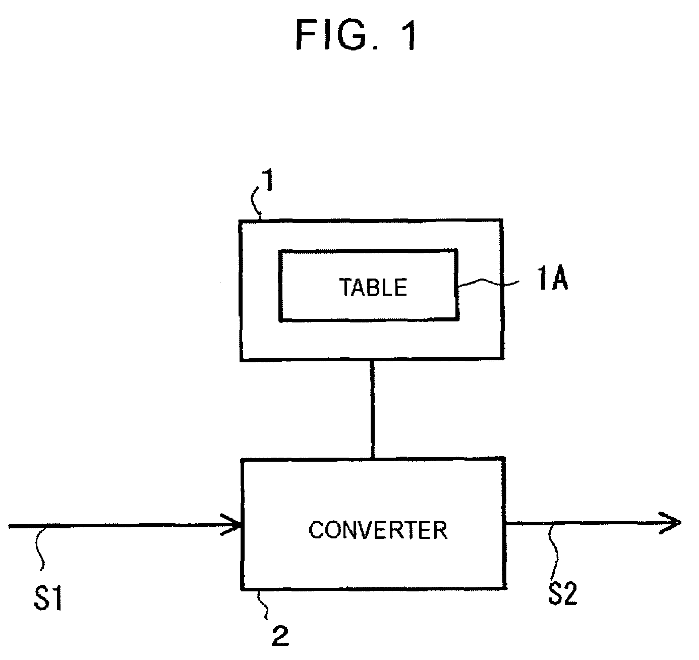
The present invention provides a technology for accurately and easily setting the ejecting positions and timing of droplets in a liquid-ejecting apparatus. This is achieved through a correspondence table between gray-scale data items and ejection pattern data items, which can be referred to when controlling the ejecting operation. The invention also includes a memory for storing the correspondence table and a converter for converting each gray-scale data item to the corresponding ejection pattern data item. The invention can provide a solution for compensating for malfunctions in ejection with a simple structure. The invention can be applied to a liquid-ejecting apparatus and a method for controlling the ejecting operation. The invention can also be recorded on a recording medium for easy reference by a computer.

Problems solved by technology

However, such a technique that generates a driving signal based on the comparison result is problematic (first problem) in that it requires a complicated circuit for the ejecting position with respect to the center of the corresponding pixel.
Such a line head is problematic (second problem) in view of the fact that an extremely a large number of nozzles are provided.
For this reason, there are cases where some of the nozzles cannot eject droplets properly.

Method used


Image

  • Ejection control device, liquid-ejecting apparatus, ejection control method, recording medium, and program
  • Ejection control device, liquid-ejecting apparatus, ejection control method, recording medium, and program
  • Ejection control device, liquid-ejecting apparatus, ejection control method, recording medium, and program

Examples


first embodiment

1. First Embodiment

[0097]1-1. Circuit

[0098]FIG. 3 is a circuit diagram of a signal processing unit according to a first embodiment of the present invention. The signal processing unit includes three main components, that is, a digital-signal processor (DSP) 11, a head controller 12, and head chips 13.

[0099]The DSP 11 receives 8-bit image data, performs multilevel error diffusion on the image data, and then converts the 8-bit image data to 4-bit gray-scale data. The gray-scale data includes information for determining the number of droplets per pixel. According to the first embodiment, one pixel corresponds to a maximum of 8 droplets.

[0100]The gray-scale data is transferred by DMA (direct memory access) to the head controller 12. In detail, the gray-scale data is transferred in sequence as 4-bit data in a range of 0 to 7 for every pixel, i.e. dot, from the first address to the n-th address corresponding to the width of the head.

[0101]A pulse number modulator (PNM) 12A converts the in...

second embodiment

2. Second Embodiment

[0131]2-1. Circuit

[0132]FIG. 5 is a circuit diagram of a signal processing unit according to a second embodiment of the present invention. The signal processing unit in FIG. 5 similarly has three components, namely, the DSP 11, the head controller 12, and the head chips 13. However, the internal structure of the head controller 12 in the second embodiment is different from that of the first embodiment. Accordingly, the differences in the internal structure of the head controller 12 will be described below.

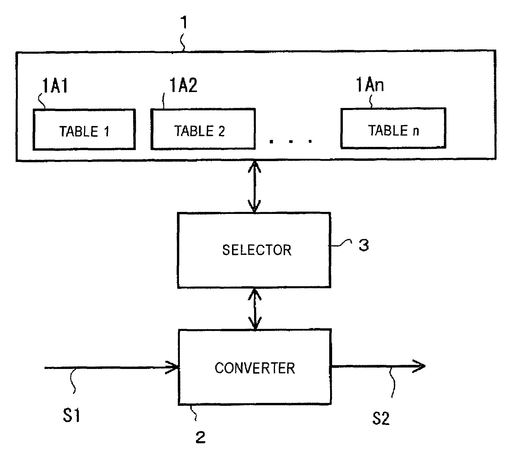
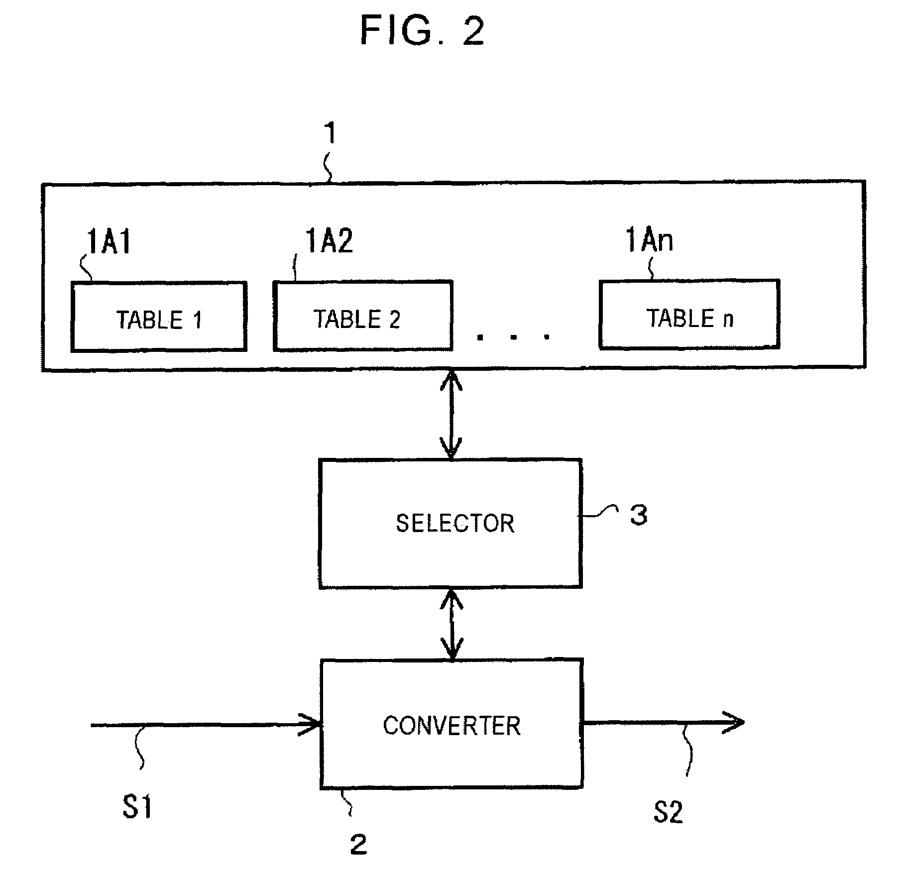
[0133]The second embodiment has two main features. One is that a plurality of look-up tables 12B1 to 12Bn for gray-scale data conversion is stored in the ejection-pattern memory 12B. The other is that the head controller 12 is provided with a table-selector 12F for selecting one of the look-up tables 12Bi (i=1 to n).

[0134]Other elements in the head controller 12, such as the PNM 12A, the buffer memory 12C, the write counter 12D, and the read counter 12E, are equ...

third embodiment

3. Third Embodiment

[0154]3-1. Circuit

[0155]FIG. 8 is a circuit diagram of a signal processing unit according to a third embodiment of the present invention. The signal processing unit in FIG. 8 similarly has three components, namely, the DSP 11, the head controller 12, and the head chips 13. However, the internal structure of the head controller 12 in the third embodiment is different from those of the first and second embodiments. Accordingly, the differences in the internal structure of the head controller 12 will be described below.

[0156]The third embodiment is basically a modification of the second embodiment. Specifically, the third embodiment is similar to the second embodiment in that the plurality of look-up tables 12B1 to 12Bn for gray-scale data conversion is stored in the ejection-pattern memory 12B and that the head controller 12 is provided with the table-selector 12F for selecting one of the look-up tables 12Bi (i=1 to n).

[0157]On the other hand, the third embodiment i...


PUM


Abstract

An ejection control device includes a memory for storing a correspondence table between gray-scale data items and ejection pattern data items, each gray-scale data item determining the number of droplets to be ejected to a corresponding pixel so as to express a desired gray-scale level of the pixel, each ejection pattern data item determining the ejection timing of droplets; and a converter for converting each gray-scale data item of the corresponding pixel to the corresponding ejection pattern data item by referring to the table. In the table, the setting of the ejecting position can be freely adjusted. In particular, an ejection pattern having ejection data bits discretely distributed for one pixel range can be easily achieved. Moreover, compliance with system changes can be achieved simply by rewriting the table.

Description

[0001]The present application claims priority to Japanese Patent Application JP2003-325867, filed in the Japanese Patent Office Sep. 18, 2003, and Japanese Patent Application JP2003-339356, filed in the Japanese Patent Office Sep. 30, 2003; the entire contents of which are incorporated herein by reference.BACKGROUND OF THE INVENTION[0002]1. Field of the Invention[0003]The present invention relates to a liquid-ejecting apparatus for ejecting droplets to an object, and to an ejection control device for controlling such an ejecting operation. Furthermore, the present invention relates to a method and a program for controlling such an ejection operation. Moreover, the present invention relates to a recording medium having the program recorded thereon.[0004]2. Description of the Related Art[0005]One of known techniques for gray-scale expression of a printing image is a pulse-number modulation technique. According to such a technique, each pixel, which is the smallest unit in an image, is...

Claims


Application Information

Patent Timeline
Patent Type & Authority Patents(United States)
IPC IPC(8): B41J29/38B41J2/07B41J2/01B41J2/205B41J2/21G06F3/12G06F17/00G06K15/00G06K15/10
CPCB41J2/2054G06K15/002G06K15/1827G06K15/102G06K2215/0094B41J2/07B41J2/21
Inventor IKEMOTO, YUICHIROTAKENAKA, KAZUYASUUSHINOHAMA, IWAOKUWAHARA, SOICHI
Owner SONY CORP
Learn More