
Radio communicate method and system

a communication method and radio communication technology, applied in the field of radio communication methods and system operating, can solve the problems of increasing the cost of such an antenna, affecting the performance of the antenna, so as to achieve the effect of high gain, large signal propagation loss, and greater sensitivity deterioration

Inactive Publication Date: 2007-11-06
NAT INST OF INFORMATION & COMM TECH
View PDF20 Cites 2 Cited by
  • Summary
  • Abstract
  • Description
  • Claims
  • Application Information

AI Technical Summary

Problems solved by technology

However, several problems arise when an actual radio system is designed and constructed.
At high frequencies; for example, in a millimeter wave band, signal propagation loss is large, and, as compared with a conventional up-converter scheme, the above-mentioned self-heterodyne scheme suffers greater deterioration in sensitivity.
This requirement increases cost of such an antenna and makes it difficult to obtain a high gain as expected.
In other words, fabrication of a wide beam antenna which has high gain and is easy to use has generally been very difficult.

Method used


Image

  • Radio communicate method and system
  • Radio communicate method and system
  • Radio communicate method and system

Examples


first embodiment

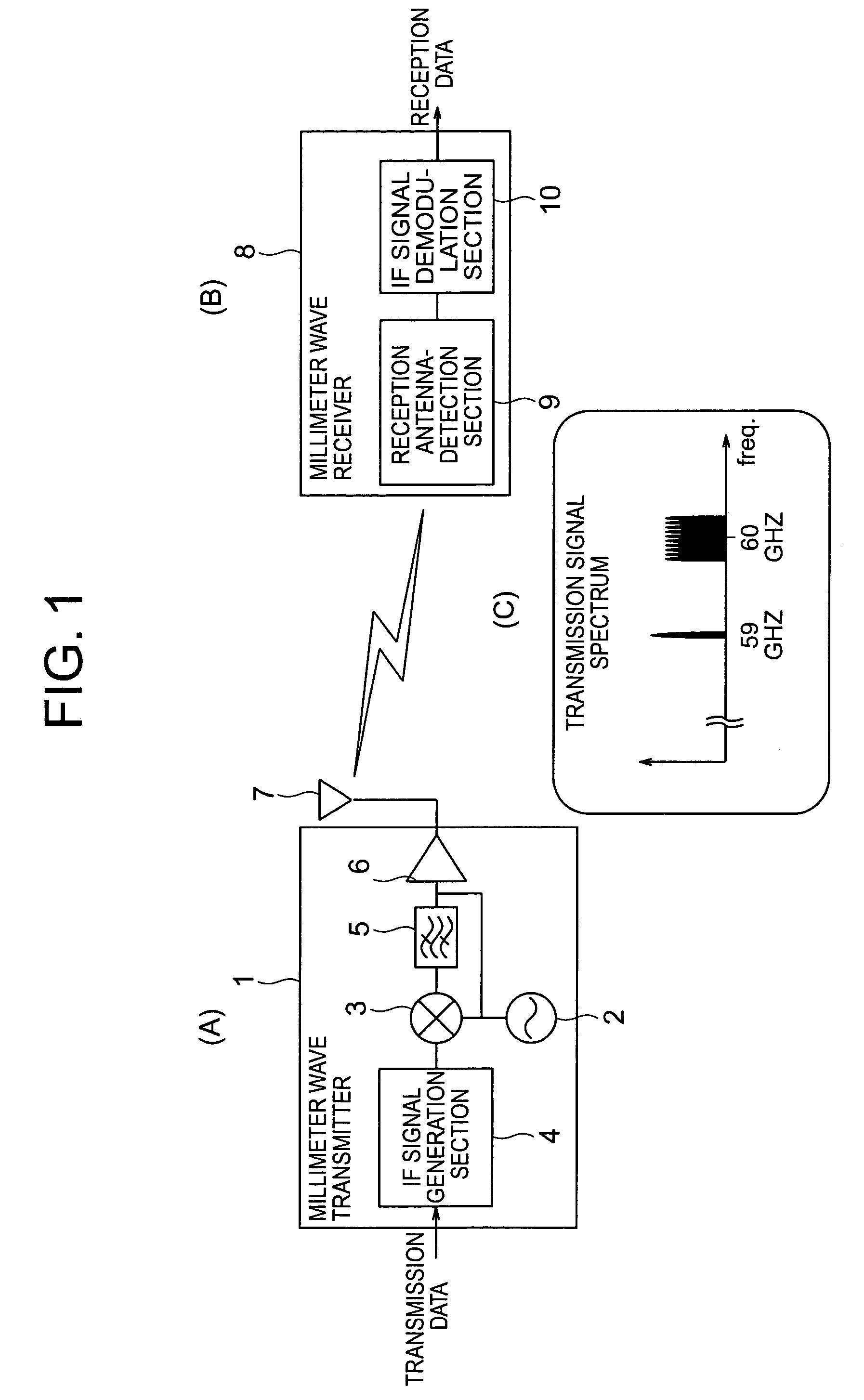
[0014]Sections (A) and (B) of FIG. 1 are diagrams showing an example configuration of a radio system according to a first embodiment of the present invention. A millimeter wave transmitter 1 includes an IF signal generation section 4 for modulating input data and outputting an IF-band modulated signal. The IF-band modulated signal is output to a mixer 3, to which a local oscillation signal is supplied from a local oscillator 2. The mixer 3 obtains a product of the IF-band modulated signal and the local oscillation signal. The thus-obtained output is passed through a band-pass filter 5 so as to remove unnecessary wave components therefrom. Thus, a radio-frequency (RF)-band modulated signal is obtained. Subsequently, a portion of power of the local oscillation signal used for the frequency conversion is added to the RF-band modulated signal. A resultant radio signal is amplified by means of an amplifier 6 and is then transmitted from an antenna 7. By virtue of the above-described tran...

second embodiment

[0016]Sections (A) and (B) of FIG. 3 are diagrams showing an example configuration of a radio system according to a second embodiment of the present invention. A millimeter wave transmitter and a millimeter wave receiver are provided in each of two stations which perform communications therebetween, whereby bi-directional radio communications are enabled. As in the first embodiment, a mixture signal containing a radio-frequency (RF)-band modulated signal and a local oscillation signal is transmitted from the transmitter of the first station. At the second station, the mixture signal is detected by the reception antenna-detection section, which the feature of the present invention, and the output of the reception antenna-detection section is input to an IF signal demodulation section so as to demodulate the reception data. At the same time, a mixture signal from the second station is received by the first station, and the reception data are demodulated.


PUM


Abstract

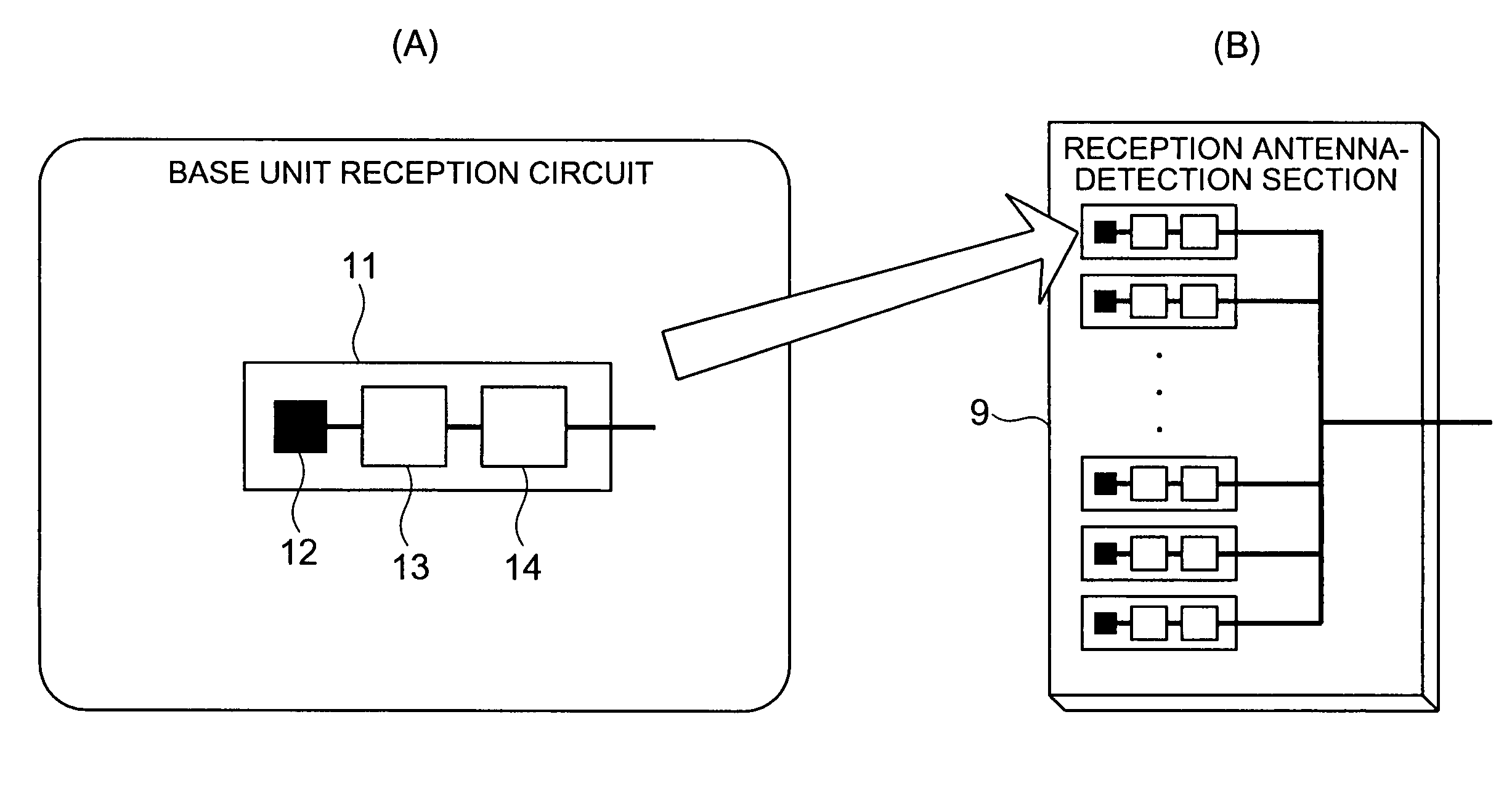
A transmitter 1 transmits from a transmission antenna 7 a mixture signal containing a radio-frequency (RF)-band modulated signal, and a portion of power of a local oscillation signal used for frequency conversion. Meanwhile, a receiver 8 detects the transmitted signal by means of a reception antenna-detection section 9. In the reception antenna-detection section 9, a plurality of base unit reception circuits 11 are disposed. Each base unit reception circuit 11 includes a planar printed antenna 12 such as a patch antenna, an amplifier circuit 13 formed on a very small planar circuit by means of an MMIC technique, and a mixer circuit 14 serving as a square-law detector. Respective outputs of the base unit reception circuits 11 are power-mixed and fed to the IF signal demodulation section. The IF signal demodulation section 10 demodulate reception data. This configuration enables realization of a reception antenna which occupies a very small space, has a detection function and a high gain, and has a wide beam characteristic comparable to that of a single-element antenna.

Description

CROSS-REFERENCE TO RELATED APPLICATIONS[0001]This application is a national phase application of International Application No. PCT / JP03 / 00116 filed on Jan. 9, 2003, and claims priority of Japan Patent Application No. 2002-093871 filed on Mar. 29, 2002.TECHNICAL FIELD[0002]The present invention relates to a radio communication method and system operating in a millimeter wave band, and more specifically, to a reception antenna used therein.BACKGROUND ART[0003]A radio communication apparatus for transmitting a high-speed digital signal or a broadband analog signal generally consists of a transmitter in which a product of an intermediate-frequency-band modulated signal (IF) and a local oscillation signal (LO) is obtained for up conversion, and a thus-generated radio-frequency modulated signal (RF) is transmitted; and a receiver in which the RF signal is received, and a product of the RF and an LO is obtained for down conversion, whereby an IF is produced. In such a case, in order to mai...

Claims


Application Information

Patent Timeline
Patent Type & Authority Patents(United States)
IPC IPC(8): H04B1/18G01S5/02G01S5/04H01Q21/08H01Q9/00H01Q1/22H01Q23/00H04B1/40
CPCH01Q1/22H01Q23/00H01Q21/08H01Q1/2208H04B1/18H04B7/08
Inventor SHOJI, YOZOHAMAGUCHI, KIYOSHITSUJI, HIROYUKIOGAWA, HIROYO
Owner NAT INST OF INFORMATION & COMM TECH
Learn More