
Webbing retractor

Active Publication Date: 2007-11-06
KK TOKAI RIKA DENKI SEISAKUSHO +1
View PDF7 Cites 37 Cited by
  • Summary
  • Abstract
  • Description
  • Claims
  • Application Information

AI Technical Summary

Benefits of technology

[0026]An object of the present invention is to provide a webbing retractor which, at a low cost, can easily stabilize the force limiter load.
[0029]Due to the rotation of the spool in the take-up direction, the tension of the webbing belt increases, and the force by which the webbing belt restrains the body of the vehicle occupant increases. In this way, movement of the body of the vehicle occupant substantially toward the front of the vehicle, which movement accompanies the inertia at the time when the vehicle rapidly decelerates, can be prevented or mitigated.
[0031]Due to the rotation of the spool being restricted, pulling-out of the webbing belt is restricted. As a result, the webbing belt reliably restrains and holds the body of the vehicle occupant.
[0033]Accordingly, relative rotation arises between the one axial direction end and the other axial direction end of the torsion shaft, and the torsion shaft deforms (is twisted). Due to this deformation, the restraining force (load) which the webbing belt applies to the body of the vehicle occupant is lessened.
[0035]Therefore, even if the torque in the pull-out direction is transmitted to the one axial direction end of the torsion shaft, the structural element of the pretensioner (i.e., the pinion) is not rotated in the pull-out direction. In this way, the pretensioner does not impede the deformation of the torsion shaft. Accordingly, the torque in the pull-out direction which is needed to deform the torsion shaft, i.e., the so-called “force limiter load”, can be set easily and accurately.

Problems solved by technology

There is the problem that it is difficult to set the load needed to deform the torsion shaft, i.e., the so-called “force limiter load”.
However, there are problems in that forming the gas vent hole in the piston and the rack bar, or forming the gas vent hole in the cylinder, is in and of itself difficult, and costs increase.

Method used


Image

  • Webbing retractor
  • Webbing retractor
  • Webbing retractor

Examples


Embodiment Construction

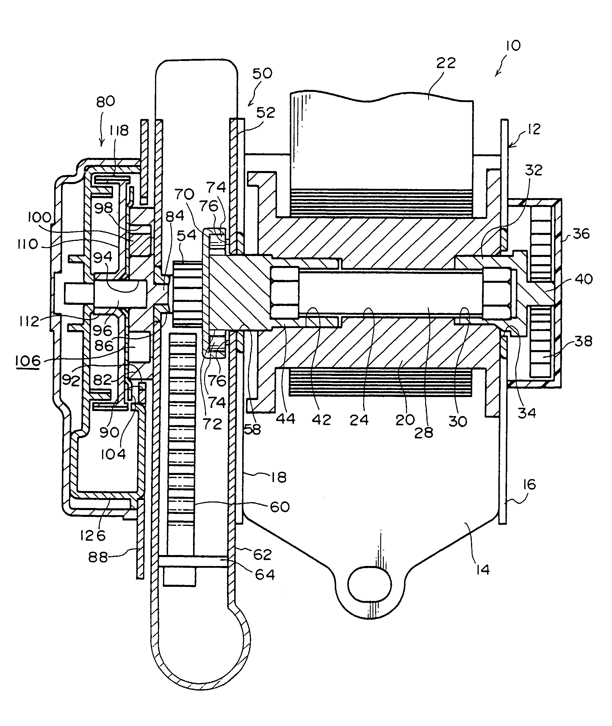
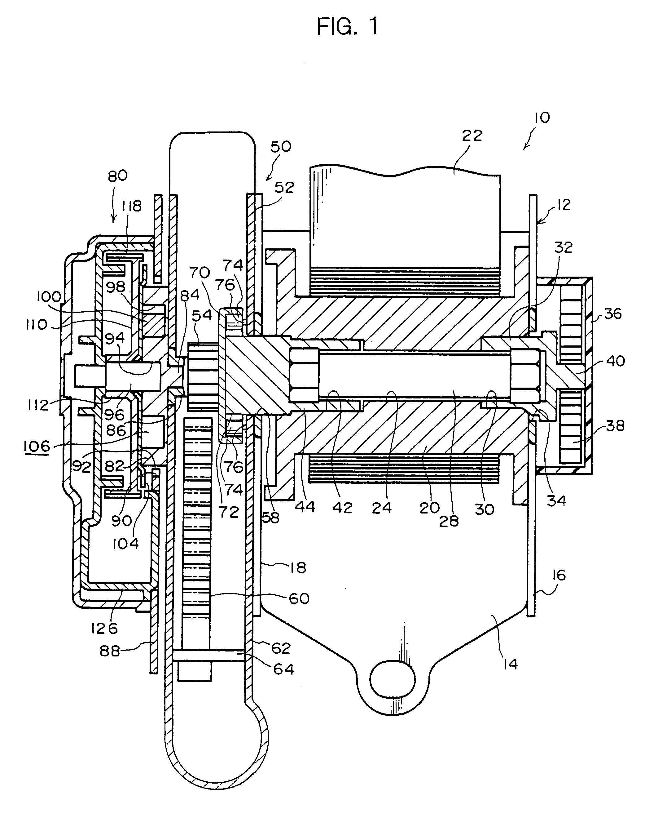
[0046]A webbing retractor of an embodiment of the present invention will be described hereinafter. Referring to FIG. 1, a webbing retractor 10 has a frame 12. The frame 12 has a flat-plate-shaped base portion 14. The webbing retractor 10 is mounted to a vehicle body by the base portion 14 being fixed to a predetermined position of the vehicle body by a fixing means such as bolts or the like.

[0047]A leg plate 16 extends from one transverse direction end of the base portion 14. A leg plate 18 extends, in the same direction as the leg plate 16 and parallel to the leg plate 16, from the other transverse direction end of the base portion 14. A spool 20 is disposed between the leg plate 16 and the leg plate 18.

[0048]The spool 20 has an axis of rotation which passes through the leg plates 16, 18 substantially orthogonally thereto, and has a substantially hollow cylindrical shape which is concentric to this axis. The longitudinal direction proximal end portion of an elongated, belt-shaped w...


PUM


Abstract

A pinion of a pretensioner is provided at a side of a torsion shaft, which side is opposite a side connected integrally to a spool via a sleeve. A base lock of a lock mechanism is connected to the pinion. Due to the lock mechanism operating, a leg plate side end portion of the torsion shaft is locked. In this way, due to operation of the pretensioner, the pinion, which is connected to a rotating portion of a sleeve, also is locked by the locking mechanism. Therefore, a piston of the pretensioner is not lowered, and internal pressure of a cylinder does not affect deformation of the torsion shaft.

Description

CROSS-REFERENCE TO RELATED APPLICATION[0001]This application claims priority under 35USC 119 from Japanese Patent Application No. 2003-138790, the disclosure of which is incorporated by reference herein.BACKGROUND OF THE INVENTION[0002]1. Field of the Invention[0003]The present invention relates to a webbing retractor which structures a seat belt device of a vehicle or the like.[0004]2. Description of the Related Art[0005]A seat belt device which restrains, by an elongated, strip-shaped webbing belt, the body of a vehicle occupant who is seated in a seat of a vehicle, is equipped with a webbing retractor which is fixed to the vehicle body at the side of the seat. The webbing retractor has a spool whose axial direction runs, for example, substantially along the longitudinal direction of the vehicle. The proximal end side, in the longitudinal direction, of the webbing belt is anchored at the spool. The webbing belt is taken-up in layers around the outer peripheral portion of the spool...

Claims


Application Information

Patent Timeline
IPC IPC(8): B65H75/48B60R22/28B60R22/405B60R22/46
CPCB60R22/4633B60R22/4676B60R22/405B60R2022/468B60R2022/287
Inventor NAGATA, TOMONORIYAMAMOTO, TOSHIMASATAKAMATSU, HITOSHIKITAZAWA, YASUHOKATO, TAKEAKISEKIZUKA, MAKOTOIMANAKA, SHIGEKAZUMATSUBAYASHI, KIYOKANEZAKI, TAKUYA
Owner KK TOKAI RIKA DENKI SEISAKUSHO
Learn More