Plasma display panel with improved cell geometry

a technology of display panel and cell geometry, which is applied in the direction of gas discharge electrodes, gas discharge vessels/containers, gas-filled discharge tubes, etc., can solve the problems of low luminous efficiency, relatively high operating voltage, and need to be resolved, so as to achieve optimum luminous efficiency and increase luminous efficiency , the effect of increasing the equivalent capacitan

Inactive Publication Date: 2007-10-30
View PDF15 Cites 2 Cited by
  • Summary
  • Abstract
  • Description
  • Claims
  • Application Information

AI Technical Summary

Benefits of technology

[0009]It is a general object of the present invention to provide a PDP cell design which provides increasing luminous efficiency.
[0010]It is another object of the present invention to provide a sustain electrode shape or dielectric film configuration that results in optimum luminous efficiency.
[0011]It is another object of the present invention to provide a plasma display cell geometry with larger equivalent capacitance at the outer part of the sustain electrodes to provide larger luminous efficiency.
[0012]In order to achieve the above objects a plasma display cell is provided which includes front and back plates, spaced sustaining electrodes on the front plate, a dielectric layer covering the sustain electrodes, an MgO layer on the dielectric layer, and address electrode on the back plate and a dielectric layer on the address electrode and a phosphor layer on the dielectric layer characterized in that the cell geometry is such that there is a larger equivalent capacitance at the outer part of the sustain electrodes to provide larger luminous efficiency. The larger equivalent capacitance is obtained by shaping the sustain electrodes or the dielectric layer deposited above the sustain electrodes.

Problems solved by technology

However, there are still problems that need to be resolved to popularize the PDP as a home commodity.
One of the most critical issues in ongoing PDP research is the improvement of the luminous efficiency, which is still low compared to conventional cathode ray tube displays.
Another important problem is the relatively high operating voltages.
PDP cells are small (cell height is ˜150 μm) and provide limited access for diagnostic measurements.
As a result, experimental studies of the transient plasma discharges in PDPs are extremely difficult, and computer-based modeling is currently essential for understanding PDP physics and optimizing its operation.

Method used


Image

  • Plasma display panel with improved cell geometry
  • Plasma display panel with improved cell geometry
  • Plasma display panel with improved cell geometry

Examples


Embodiment Construction

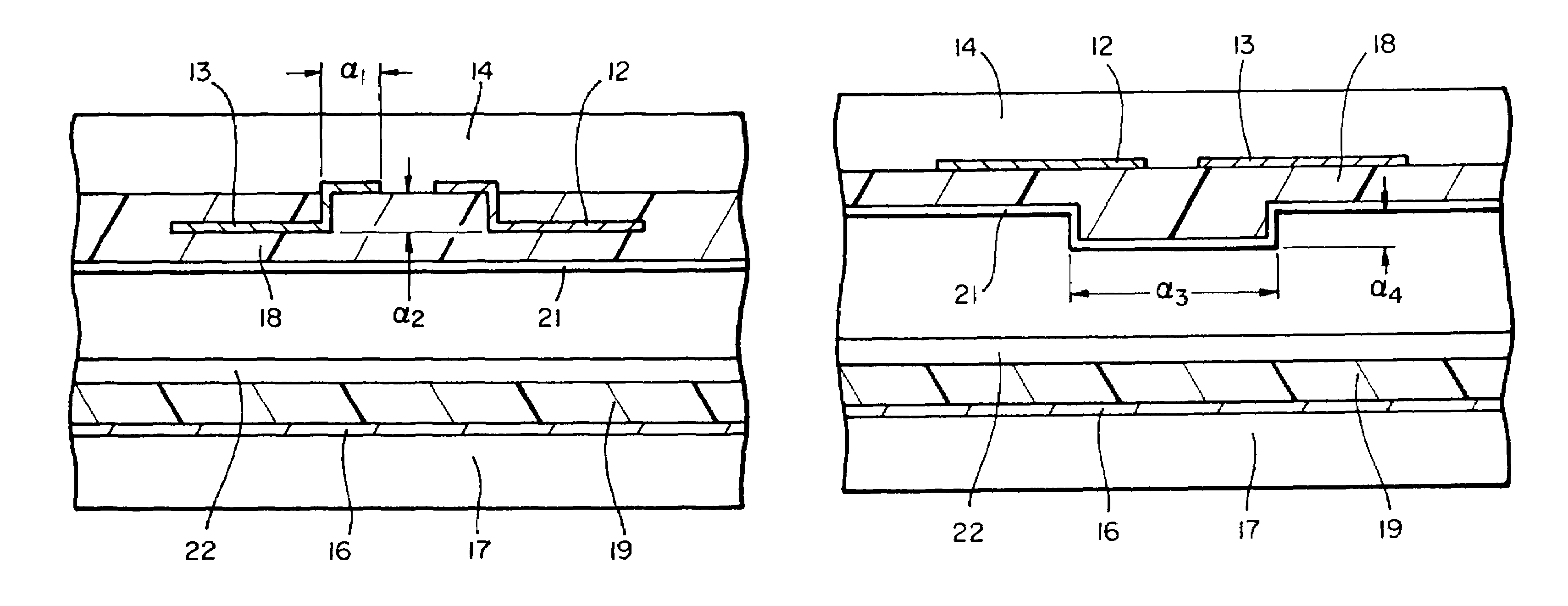
[0027]The geometry of a standard coplanar-electrode PDP cell used in the following discussion is shown by the cross sectional view in FIG. 2. The cell consists of two sustain electrodes, 12 and 13, separated from the gas by dielectric layer 18. A MgO layer 21 is deposited on the dielectric film. The bottom of the cell consists of the address electrode 16 separated from the gas by dielectric layer 19 with a phosphor layer 22 on top. The output window of the device is the top side of the upper dielectric layer, noting that the sustain electrodes are transparent. In the following discussions the gas mixture filling the region between the dielectric layers is a Xe—Ne mixture with 4% Xe at a pressure of 500 Torr. The height and width of the cell are H=210 μm and L=1260 μm, respectively. Our reference case is characterized by the parameter values g=100 μm, w=300 μm, d1=d2=30 μm, and εr=10, where g is the electrode gap length, w is the sustain electrode width, d1, d2 are the thickness of t...


PUM


Abstract

A cell geometry for a coplanar electrode plasma display panel consisting of two transparent plates, one with parallel sustain electrodes, and the other with address electrodes deposited on their surface. The electrodes are covered with a dielectric film. A protective MgO layer is deposited on the dielectric film adjacent the sustain electrodes. A phosphor layer is deposited on the other dielectric film. The plates are scaled together with their electrodes at right angles and the gap between the plates is filled with an inert gas mixture. The geometry of the sustain electrodes and / or associated dielectric film provides a larger equivalent capacitance at the outer part of the sustain electrodes to provide larger luminous efficiencies.

Description

RELATED APPLICATIONS[0001]This application claims priority to U.S. Provisional Application Ser. No. 60 / 364,401 filed Mar. 12, 2002.BRIEF DESCRIPTION OF THE INVENTION[0002]This invention relates generally to cells of plasma display panels and more particularly to cell geometries which provide improved luminous efficiency.BACKGROUND OF THE INVENTION[0003]Plasma display panels (PDPs) are one of the leading candidates in the competition for large-size, high-brightness, high-contrast-ratio flat panel displays, suitable for high definition television (HDTV) wall-mounted monitors. Their advantages are high resolution, wide viewing angle, low weight, and simple manufacturing process for fabrication.[0004]Recent progress of PDP technology development and manufacturing has been remarkable. However, there are still problems that need to be resolved to popularize the PDP as a home commodity. One of the most critical issues in ongoing PDP research is the improvement of the luminous efficiency, w...

Claims


Application Information

Patent Timeline
Patent Type & Authority Patents(United States)
IPC IPC(8): H01J17/49H01J11/12H01J11/24H01J11/38
CPCH01J11/12H01J11/38H01J11/24H01J2211/245
Inventor INAN, UMRAN S.VERONIS, GEORGIOS
Why Eureka
Try Eureka