
Ink bag, ink cartridge and ink-jet recording apparatus, ink filling method, ink refilling method, manufacturing method of ink cartridge, and recycling method of ink cartridge

a technology of ink cartridges and ink cartridges, which is applied in the field of ink cartridge manufacturing methods, ink cartridge recycling methods, and ink cartridge filling methods, can solve the problems of serious waste of resources, increased ink cartridge size, and increased ink cartridge size, and achieves convenient ink filling, easy mounting, and reduced waste of unused ink

Inactive Publication Date: 2007-10-30
RICOH KK
View PDF21 Cites 22 Cited by
  • Summary
  • Abstract
  • Description
  • Claims
  • Application Information

AI Technical Summary

Benefits of technology

The present invention provides an ink bag and ink cartridge that minimize waste of unused ink and are easy to mount and detach with stability. The ink bag has a flexible bag body with an ink filling opening and an ink discharge port, and a holding member attached to one edge of the bag body. The holding member has an engagement part for holding the ink bag in a cartridge case. The ink bag can be easily filled and refilled with ink, and the ink cartridge can be recycled. The ink bag holding method and the ink refilling method are also provided. The technical effects of the invention include reducing waste of ink, simplifying the ink cartridge assembly process, and improving the recycling of ink cartridges.

Problems solved by technology

Meanwhile, in recent ink-jet recording apparatuses, the required picture quality is increasing, and associated with this, the ink consumption is increasing also.
Under such a situation, there arises a problem, in a conventional ink-jet recording apparatus in which the ink cartridge is mounted on a carriage, in that frequent exchange ink cartridge becomes necessary.
Thus, the size of the ink cartridge is increasing, while such an increase of the size of the ink cartridge raises the problem in that mere discarding of used ink cartridge as in the case of the ink cartridge described in the Japanese Laid Open Patent Application 10-202901 causes the problem of serious waste of resources.
In view of the situation noted above, there is proposed an ink cartridge in the Japanese Laid Open Patent Application 10-202900 that allows detachable accommodation of the ink tank in the chassis part, while such a conventional construction has a drawback in that the ink tank is unstable and stable supply of the ink is difficult.
Thus, such a front loading structure cannot be used.
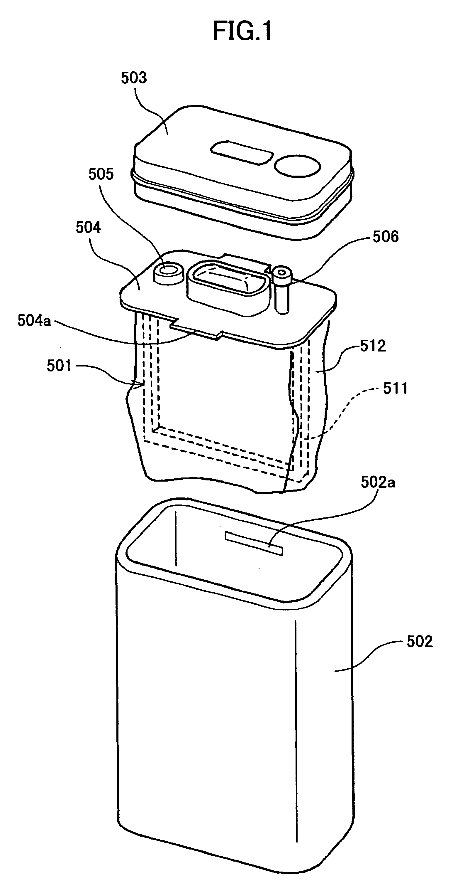
Furthermore, with the ink cartridge shown in FIG. 1, there arises a problem poor operability when assembling or deassembling the cartridge in view of the fact that it becomes necessary to push the holding member formed integral with the frame body of the ink storage part into the cylindrical case having an opening generally the same size of the holding member and then to pull out the holding member from the cylindrical case.
Also, there exists a problem of poor stability when supplying ink by removing the ink storage part from the cylindrical case together with the holding member.
Further, in the case the ink is supplied in the state in which the ink storage part is mounted to the cylindrical case together with the holding member, there arises a problem in that it is not possible to confirm the status of the ink storage part.
Thus, there is a problem in such a construction that refilling of the ink is difficult.
Further, because of the construction of the ink storage part of FIG. 1 in which the film-like member 512 is attached to the frame body 511 forming a unitary body with the holding member 504, there arise problems such as a gap being formed easily between the frame body 511 and the film-like member 512, and it is difficult to apply external pressure to the film-like member 512, leading to the problem that unused ink tends to remain in the ink storage part.
On the other hand, in the case the ink storage part is constructed in the form of flexible bag, it becomes necessary to provide a protection cover for improving load / unload operability to and from the recording apparatus main body and further for improving durability, while such a necessity raises the problem of providing a construction enabling easy loading and unloading of the flexible ink bag having a protective cover at the time of refilling of the ink.

Method used


Image

  • Ink bag, ink cartridge and ink-jet recording apparatus, ink filling method, ink refilling method, manufacturing method of ink cartridge, and recycling method of ink cartridge
  • Ink bag, ink cartridge and ink-jet recording apparatus, ink filling method, ink refilling method, manufacturing method of ink cartridge, and recycling method of ink cartridge
  • Ink bag, ink cartridge and ink-jet recording apparatus, ink filling method, ink refilling method, manufacturing method of ink cartridge, and recycling method of ink cartridge

Examples


first embodiment

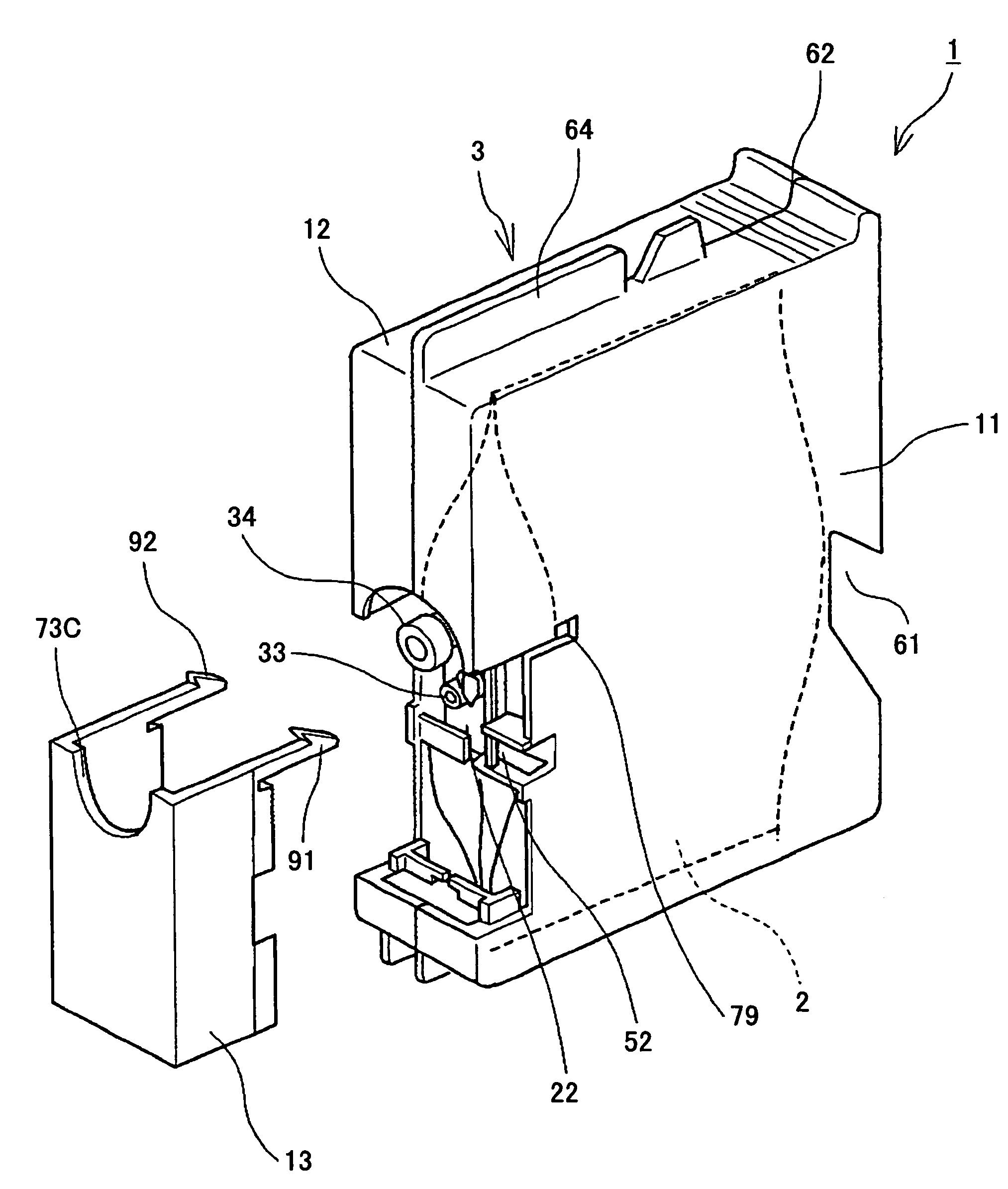
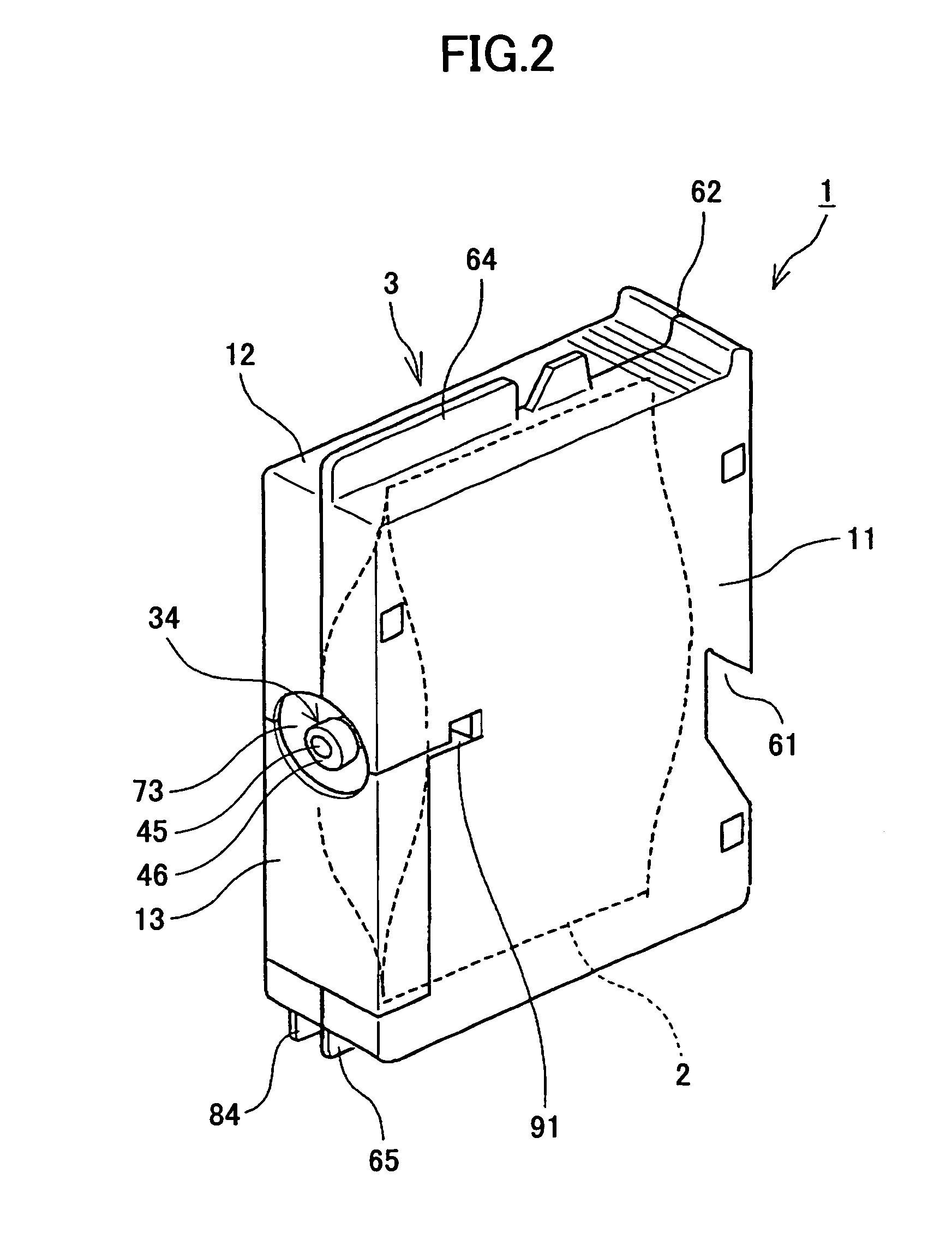
[0086]FIG. 2 is a diagram showing an appearance of an ink cartridge according to the present invention in an oblique view, FIG. 3 is a schematic oblique view showing the ink cartridge of FIG. 2 in the state in which a third case part is removed, FIG. 4 is a front cross-sectional view of the same ink cartridge.

[0087]Referring to the drawings, this ink cartridge 1 includes an ink bag 2 filled with ink and a case 3 accommodating the ink bag 2. The case 3 is formed of a first case part 11, a second case part 12 and a third case part 13, wherein the first case part 11 and the second case part 12 form together a case part acting as a protection cover protecting a side of the ink bag 2. Thus, the case 3 accommodating the ink bag 2 is split into the first case part 11 and the second case part 12 along a plane parallel to the ink supply direction (ink discharge direction).

[0088]First, an example of the ink bag 2 of the present invention will be explained with reference to FIGS. 5 through 13,...

second embodiment

[0158]Next, another example of the ink bag of the present invention will be explained with reference to FIGS. 19 through 21, wherein FIG. 19 is a side view diagram of the ink bag, FIG. 20 is an oblique view diagram showing the same ink bag in the state filled with ink, while FIG. 21 is a bottom view diagram of the ink bag of FIG. 20.

[0159]It should be noted that this ink bag 2 includes the bag body 21 of two aluminum laminate films 30 and 30, wherein there is further provided a rear part (bottom part) 21a at the rear side also formed of the aluminum laminate film. By using such three sheets of aluminum laminate films 30, the capacity of ink bag 2 can be increased.

[0160]Next, the construction of the case of the ink cartridge 1 of the present embodiment will be explained withi reference to FIGS. 22 and 23, wherein it should be noted that FIG. 22 is a side view diagram of the first case part 11 of the ink cartridge 1, while FIG. 23 is a side view diagram of the second case part 12 of t...

third embodiment

[0188]Next, other embodiment of the ink cartridge 1 will be explained with reference to FIGS. 25-30.

[0189]The embodiment of FIG. 25 reinforces the engagement between the catching nail 91 and the first case part 11 and the second case part 12 of the third case part 13 by sticking a label 101 on the outside of the first case part 11 and the second case part 12. With this, it becomes possible to prevent dropping of the third case part 13 even in the case the ink cartridge 1 is inserted and removed frequently.

[0190]It should be noted that the embodiment of FIG. 26 fixes the first case part 11 and the second case part 12 by tightening a screw member 102. With this, disassembling of the case 3 is prevented even in the case in which the ink cartridge 1 is inserted and removed frequently.

[0191]In the embodiment of FIG. 27, there are formed cutout parts 69A and 69B respectively on the first case part 11 and the second case part 12 so as to be located at the lateral side of the discharge port...


PUM


Abstract

An ink bag comprises a flexible bag body of a generally rectangular form and a holding member attached to one edge of the bag body, wherein the holding member includes: an ink filling opening for filling the bag body with ink; an ink discharging opening for discharging the ink inside the bag body; and an engaging part for holding the ink bag to a cartridge case in which the ink bag is accommodated.

Description

TECHNICAL FIELD[0001]The present invention relates to ink bag, ink cartridge structure and ink-jet recording apparatus, ink filling method, ink refilling method, manufacturing method of ink cartridge and recycling method of ink cartridge.BACKGROUND ART[0002]An ink-jet recording apparatus is used extensively for image formation apparatuses (called also as image recording apparatus) such as printers, facsimiles, copiers, and the like.[0003]An ink-jet recording apparatus carries out recording of images on a sheet by discharging ink from a recording head. Here, sheet is not limited to paper but also includes OHP sheet, and the like. Thus, “sheet” represents the medium on which images are formed and is also called as medium to be recorded or recording medium, or recording paper. An ink-jet recording apparatus has various advantageous features such as capability of recording high-definition images at high speed, low running cost, little noise, and capability of recording color images easi...

Claims


Application Information

Patent Timeline
Patent Type & Authority Patents(United States)
IPC IPC(8): B41J2/175
CPCB41J2/17513B41J2/17523B41J2/17556B41J2/17553B41J2002/17516B41J2/175
Inventor MURANAKA, MASAKAZUSUZUKI, MASATOTSUYUKI, TAKANORIIGUCHI, MASAMI
Owner RICOH KK
Learn More