
Method and program product for determining a radiance field in an optical environment

a technology of optical environment and radiance field, applied in the direction of optical radiation measurement, photometry using electric radiation detectors, instruments, etc., can solve the problems of requiring a large amount of data manipulation, long monte carlo calculation, and no analytic solution for rte, so as to achieve efficient and finer processing of information and quickly determine the characteristics of an optical environment

Inactive Publication Date: 2007-10-23
SOUTH FLORIDA UNIVESITY OF
View PDF21 Cites 19 Cited by
  • Summary
  • Abstract
  • Description
  • Claims
  • Application Information

AI Technical Summary

Benefits of technology

"The present invention is a method and program product for determining a radiance field in an optical environment using Monte Carlo techniques. The invention allows for the rapid and accurate determination of the radiance field for a given set of parameters, which is useful for researchers and other personnel in various fields such as physical science and remote sensing. The invention can approximate the solution of the Radiative Transfer Equation (RTE) in arbitrary one, two, or three-dimensional environments, making it more efficient and finer processing of information. The method and program product can also predict the efficacy of instrumental measurements and provide a set of parameters for given situations. Overall, the invention allows for the efficient and accurate determination of the optical environment and the ability of optical instruments to perform analysis for given conditions."

Problems solved by technology

Unfortunately, the RTE supplies no analytic solution for problems characterized by realistic geometries, boundary conditions and optical parameters.
However, Monte Carlo calculations are also long and cumbersome in nature and require a great amount of data manipulation.

Method used


Image

  • Method and program product for determining a radiance field in an optical environment
  • Method and program product for determining a radiance field in an optical environment
  • Method and program product for determining a radiance field in an optical environment

Examples


Embodiment Construction

[0027]The present inventions now will be described more fully hereinafter with reference to the accompanying drawings, in which some, but not all embodiments of the invention are shown. Indeed, these inventions may be embodied in many different forms and should not be construed as limited to the embodiments set forth herein; rather, these embodiments are provided so that this disclosure will satisfy applicable legal requirements. Like numbers refer to like elements throughout.

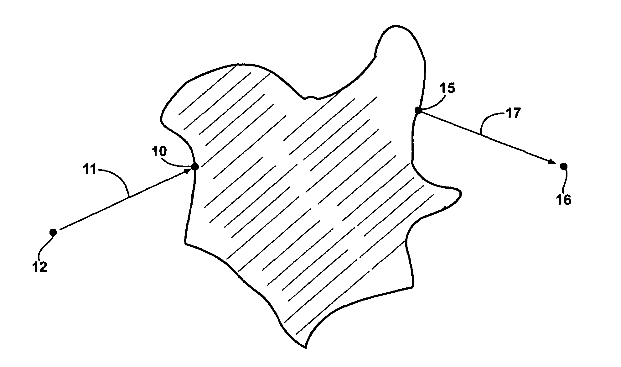
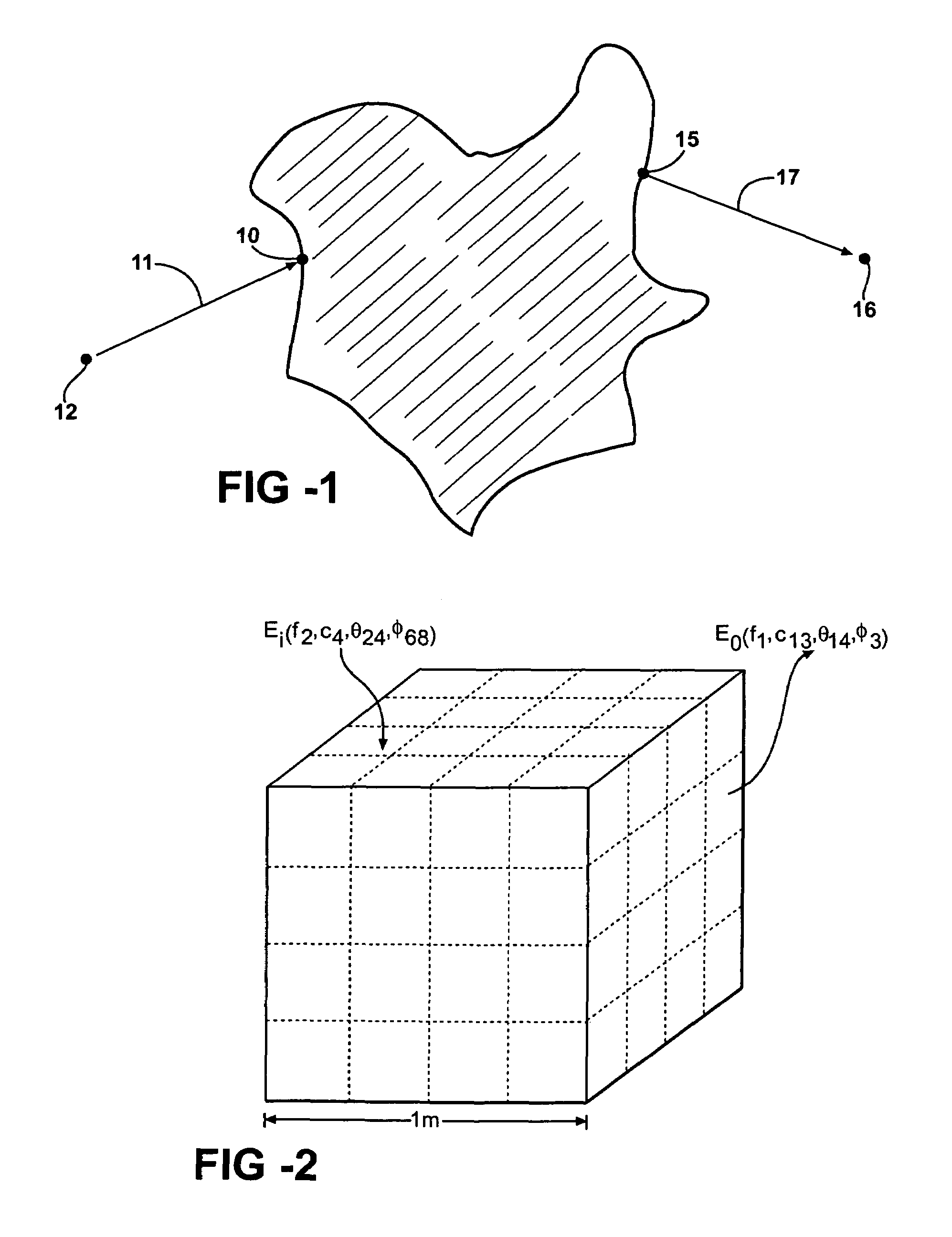
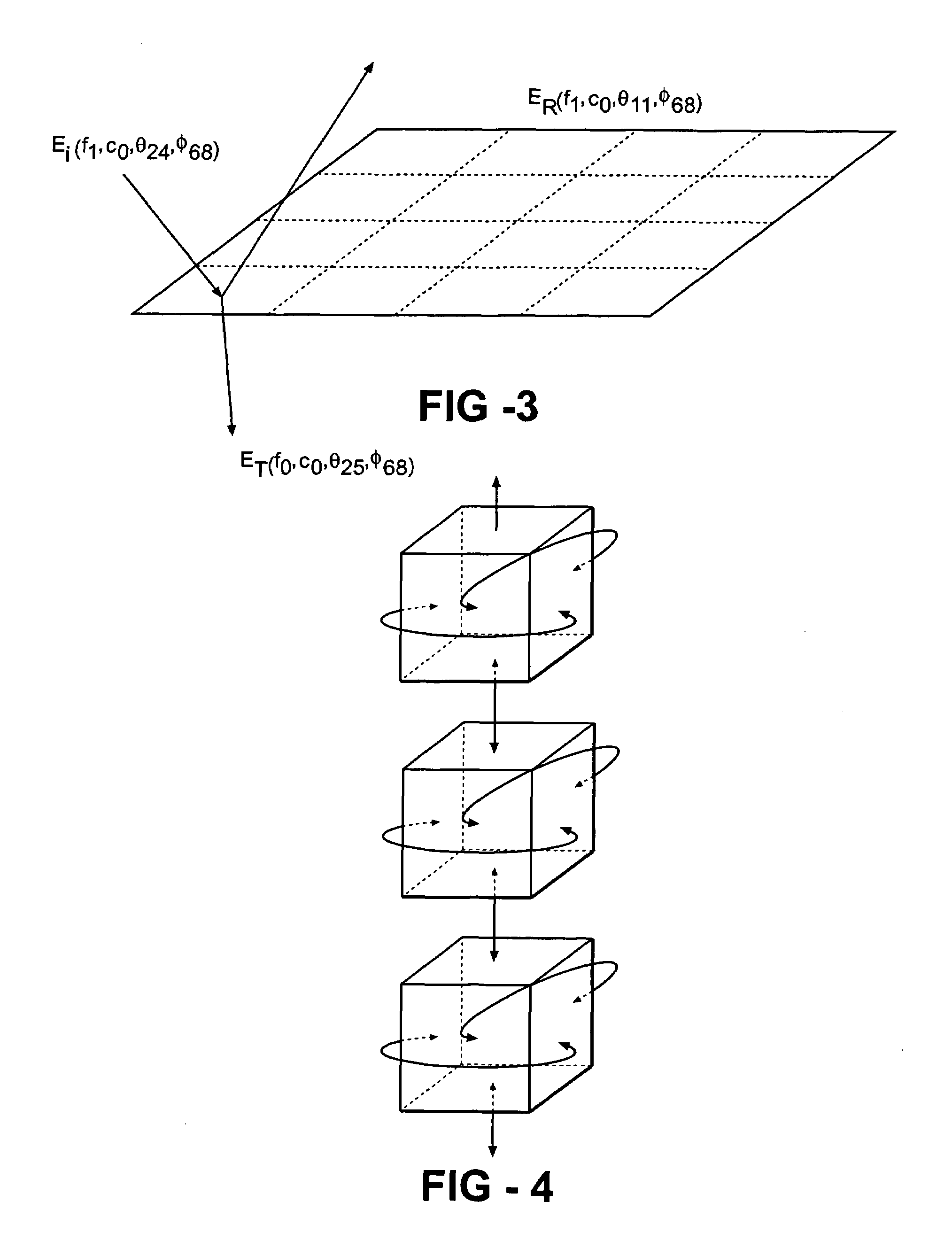
[0028]The present invention includes a method and program product for determining a radiance field in an optical environment. Generally, the method and program product generate a model of the optical environment, partition the modeled, optical environment into discreet, contiguous regions, or elements, and apply Monte Carlo techniques to determine an optical response function for each region for which the optical response function cannot be analytically defined. The optical response function provides an output ...


PUM

PropertyMeasurementUnit
grid sizeaaaaaaaaaa
zenith angleaaaaaaaaaa
concentrationsaaaaaaaaaa

Abstract

A hybrid method is presented by which Monte Carlo techniques are combined with iterative relaxation techniques to solve the Radiative Transfer Equation in arbitrary one-, two- or three-dimensional optical environments. The optical environments are first divided into contiguous regions, or elements, with Monte Carlo techniques then being employed to determine the optical response function of each type of element. The elements are combined, and the iterative relaxation techniques are used to determine simultaneously the radiance field on the boundary and throughout the interior of the modeled environment. This hybrid model is capable of providing estimates of the under-water light field needed to expedite inspection of ship hulls and port facilities. It is also capable of providing estimates of the subaerial light field for structured, absorbing or non-absorbing environments such as shadows of mountain ranges within and without absorption spectral bands such as water vapor or CO2 bands.

Description

RELATED APPLICATIONS[0001]This patent application claims priority to and all advantages of U.S. Provisional Patent Application 60 / 497,666, which was filed on Aug. 25, 2003.STATEMENT OF GOVERNMENT INTEREST[0002]The work that led to this invention has been in supported in part by a grant from NASA, Grant Number NAS 5-31716. Thus, the United States Government may have certain rights to this invention.FIELD OF THE INVENTION[0003]The present invention generally relates to a method and program product for determining a radiance field in an optical environment. The present invention more specifically relates to a method and program product that applies Monte Carlo techniques to determine the radiance field in the optical environment.BACKGROUND OF THE INVENTION[0004]In the many fields of physical science in which researchers deal with aspects of radiative transfer, one important task is to determine the direction and intensity of radiant energy transport within a region of interest, given: ...

Claims


Application Information

Patent Timeline
Patent Type & Authority Patents(United States)
IPC IPC(8): G01N21/47G01J1/42G06T15/50G01N21/49
CPCG01N21/49
Inventor REINERSMAN, PHILLIP N.CARDER, KENDALL L.
Owner SOUTH FLORIDA UNIVESITY OF
Learn More