Gravitational pressure regulating mechanism

a gravity-regulated mechanism and gravity-regulated technology, applied in the field of shunt valves, can solve the problems of shunt system failure to satisfactorily solve, csf overflow, shunt malfunction and revision, etc., and achieve the effects of non-magnetic, reliable and precise, and simple to make and us

Inactive Publication Date: 2007-10-16
SOPHYSA SA
View PDF45 Cites 3 Cited by
  • Summary
  • Abstract
  • Description
  • Claims
  • Application Information

AI Technical Summary

Benefits of technology

[0022]The present invention provides a device that is simple to make and use, is reliable and precise, and is nonmagnetic so as not to compromise CT and MRI images. In addition, the present invention permits independent use or use in combination with standard valve systems to compensate for their functional deficiencies while permitting a physician to use a valve mechanism that he or she is familiar with. Finally, the device provides an increased level of safety for the patient.
[0024]The present invention is directed to a gravitational pressure regulating mechanism for use with a valve for control of pressure and diversion of bodily fluids. In a first preferred embodiment, a gravitational pressure regulating mechanism for control of pressure and diversion of bodily fluids is provided which includes a reservoir having an entry port and an exit port, a free floating weight adapted to freely slide in the reservoir from a closed position wherein the weight blocks the entry port to an opened position wherein the weight is positioned away from the entry port and a cap to seal the exit port. The mass of the free floating weight is proportional to the amount of resistance to flow of the bodily fluids through the regulating mechanism. Preferably, the free-floating weight is generally cylindrical in shape. Finally, the weight may have an aperture extending through it to permit a minimal flow of bodily fluids entering from the exit port to the exit port while the weight is in the closed position.
[0026]The floor of the reservoir is preferably generally conically-shaped with the entry port at the center of conically-shaped floor. Preferably, the reservoir and free-floating weight are manufactured from biocompatible non-ferrous materials,preferably of greater than or equal specific gravity than stainless steel such as Elgiloy®, Phynox™, or tantalum. The surface adapted to engage the entry port when the weight is in the closed position may be constructed in an integral unit with the weight or separately attached to the weight. The surface may be a protrusion having a shape that is, for example, conical, flat, hemispherical, curved, tapered, or needle. The closure member of the weight may help to center the weight in the reservoir.
[0027]The weight may have a series of channels to permit unrestricted flow of a portion of the bodily fluids entering the mechanism from the entry port to the exit port. Preferably, the cap is constructed from an elastomeric material. Additionally, preferably, the closure member is constructed from sapphire, ruby, or synthetic ceramic, and, more preferably, from one of these materials in the shape of a hemisphere. It is desirable that the distance between an end of the weight opposite the closure member and an inside surface of the elastomeric cap is less than a height of the weight. Finally, the weight may have an aperture extending through it to permit a minimal flow of bodily fluids entering from the exit port to the exit port while the weight is in the closed position.

Problems solved by technology

However, problems such as overdrainage of CSF continues to be a major cause of shunt malfunction and revision.
These shunt systems do not satisfactorily solve a problem brought about by the pressure drop which results when the patient shifts from a substantially horizontal to a substantially vertical position.
However, in the case of a patient fitted with a lumbar peritoneal shunt system, the hydrostatic head, working upon the check valve, increases abruptly when he moves from a horizontal to vertical position, and the pressure increase causes the valve to open.
The result is excessive rate of drainage.
Unfortunately, a high rate of complications due to both under and over drainage still occurred with the use of an anti-siphon device.
The above designs suffer from several problems.
First, they depend upon an elastomeric membrane, which, by virtue of the properties of elastomers, tend to increase in stiffness over time, thereby changing the functional properties of the membrane.
Furthermore, these devices are generally implanted on the cranium under the scalp, and may be occluded by the weight of the skull resting on the device when the patient is recumbent.
Finally, in order for these devices to be sufficiently sensitive to changes in pressure, the membranes must be very thin and delicate.
They may be easily damaged or destroyed by puncture with a needle, which may occur whenever CSF samples are taken or medication is administered through the shunt.
Unfortunately, this device is bulky and highly position sensitive, and only works properly in the vertical position.
An additional problem was that the cylinder and balls, as well as the differential valve mechanism, were made of stainless steel, which causes an artifact on CT or MRI imaging.
This is especially troublesome, as lumbar catheter placement leads to a higher complication rate of spine problems, thereby necessitating imaging of the exact area which is compromised by the magnetic implant.
Additionally, this device was manufactured from stainless steel thereby compromising CT and MRI images.

Method used


Image

  • Gravitational pressure regulating mechanism
  • Gravitational pressure regulating mechanism
  • Gravitational pressure regulating mechanism

Examples


Embodiment Construction

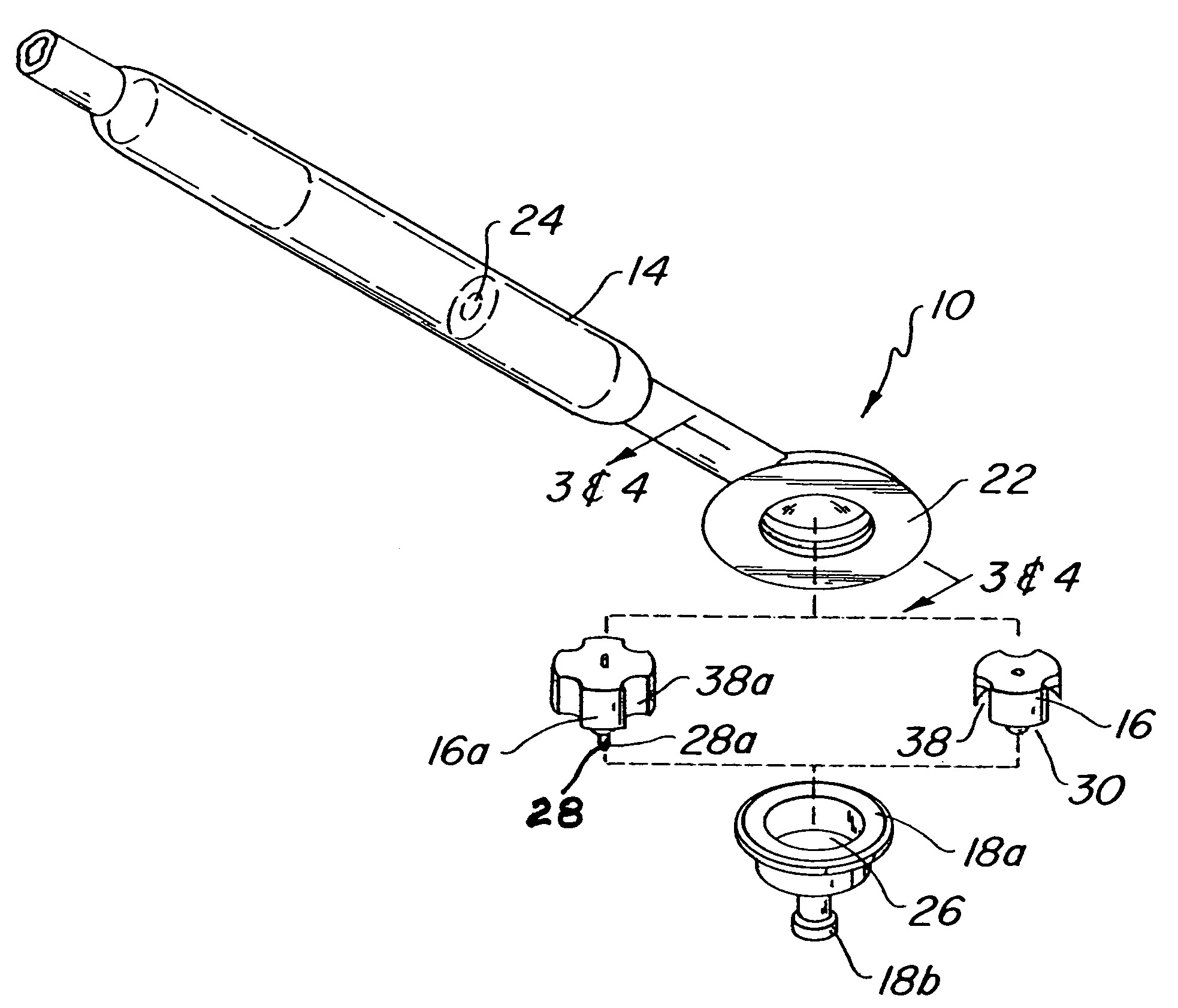
[0037]Referring now to the drawing figures, wherein like part numbers refer to like elements throughout the several views, there is shown in FIG. 1, a gravitational pressure regulating mechanism 10 as attached to a human being 12 which also includes a valve assembly 14. The gravitational pressure regulating mechanism 10 is mounted to the crown of the skull in a hole drilled into the crown and is a attached to a catheter 15 that is introduced into the ventricle 13 within the brain. Placement of the reservoir on the crown of the head is necessary. Frontal horn catheter placement is preferable. As seen in FIG. 1, fluid is drained through the regulating mechanism 10, through valve assembly 14 and into a remote part of the body, as known to those skilled in the art for similar devices.

[0038]As can be seen in FIGS. 2-5, the gravitational pressure regulating mechanism 10 consists of a free-floating weight 16, contained within a rigid reservoir 18. The reservoir 18 has a first end 18a and a...


PUM


Abstract

A gravitational pressure regulating mechanism for use with a valve is provided for control of pressure and diversion of bodily fluids. The mechanism includes a reservoir having first and second ends, the first end being open and the second end having a floor and an entry port, and a free floating weight adapted to freely slide in the reservoir from a closed position wherein the weight is adjacent the floor to an opened position wherein the weight is positioned away from the floor. The weight has a closure member having a surface to engage the entry port when the weight is in the closed position. The mechanism further includes a cap having an exit port to seal the open first end of the reservoir. The mass of the weight is proportional to the amount of resistance to flow of the bodily fluids through the regulating mechanism.

Description

BACKGROUND OF THE INVENTION[0001]This invention relates to a shunt valve for draining of cerebrospinal fluid.[0002]In the treatment of hydrocephalus, it has been customary to drain excess cerebrospinal fluid (CSF) from one site in the body to another. For example, a catheter may be introduced into the ventricle within the brain and connected through a pressure operated check valve to a subcutaneous catheter so that the CSF is introduced into the blood stream or the peritoneal cavity. Alternatively, a catheter may be inserted into the body adjacent the spine and connected through a check valve to a catheter inserted in the peritoneal cavity. The latter is commonly termed a lumbar peritoneal shunt system and may be employed only upon patients afflicted with communicating hydrocephalus in which the excess CSF is not confined to the cranium, but is present in the region of the spine.[0003]The invention of the first functioning hydrocephalus shunt was made in 1956 as disclosed in U.S. Pa...

Claims


Application Information

Patent Timeline
Patent Type & Authority Patents(United States)
IPC IPC(8): A61M5/00A61M27/00
CPCA61M27/006A61M5/14A61M5/142A61M31/00A61M37/00
Inventor HOKANSON, CHARLES P.SMITH, BRADLEY S.
Owner SOPHYSA SA
Why Eureka
Try Eureka