
Cable crossover exercise apparatus

Inactive Publication Date: 2007-10-16
ICON HEALTH & FITNESS INC
View PDF81 Cites 70 Cited by
  • Summary
  • Abstract
  • Description
  • Claims
  • Application Information

AI Technical Summary

Benefits of technology

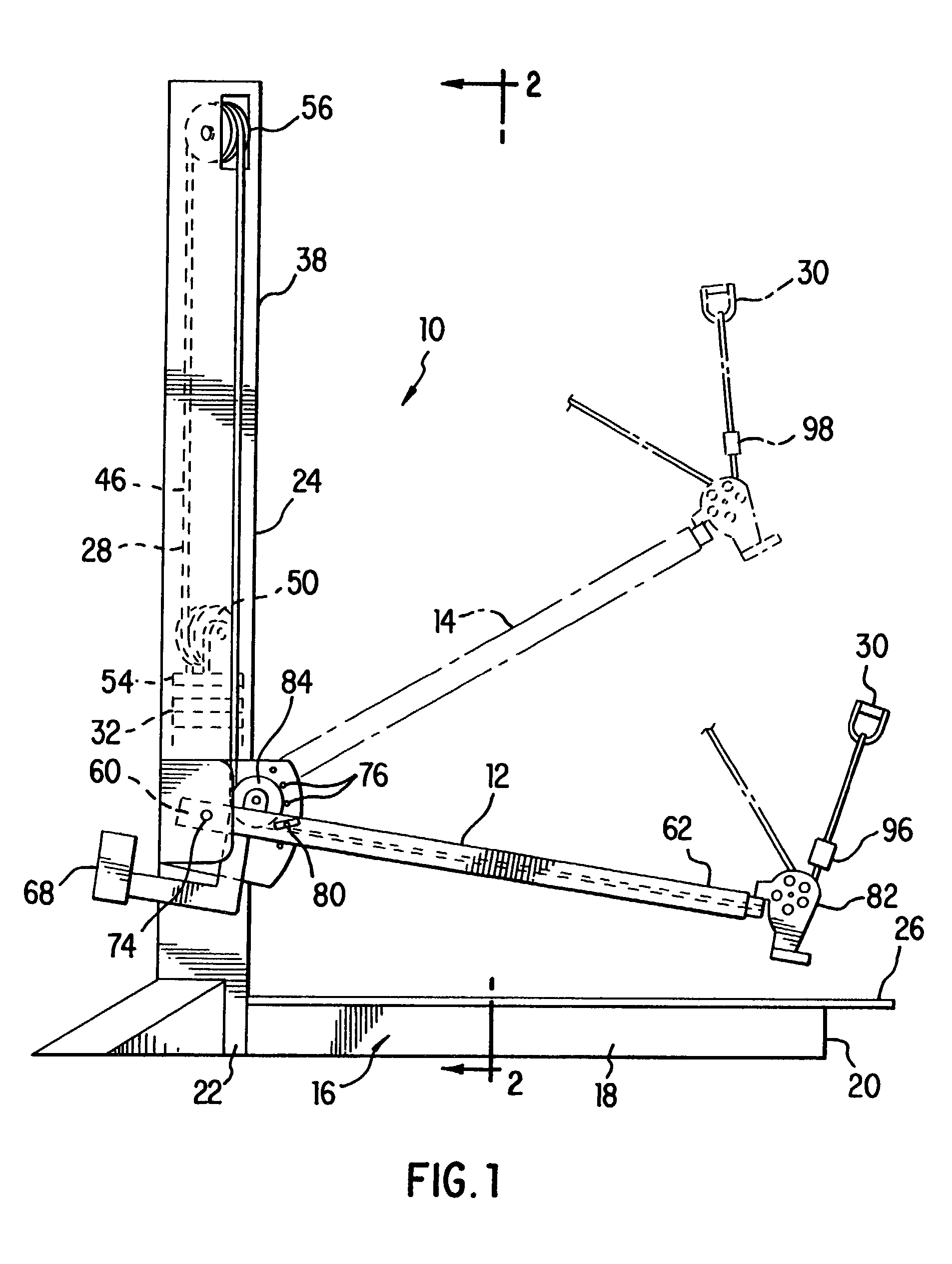
[0010]It is, therefore, an object of the present invention to provide an exercise apparatus including a resistance assembly and a cable linking a first extension arm and a second extension arm to the resistance assembly. The first extension arm includes a first end selectively supported adjacent the resistance assembly and a free second end from which the first strand of the cable system extends for engagement by a user. Similarly, the second extension arm includes a first end selectively supported adjacent the resistance assembly and a free second end from which the second strand of the cable system extends for engagement by a user. The first extension arm extends away from the second extension arm, moving the second end of the first extension arm away from the second end of the second extension arm to define an extended opposed spacing of the first and second strands.
[0011]It is also an object of the present invention to provide an exercise apparatus wherein the first extension arm and the second extension arm are substantially parallel as they extend from the resistance assembly.
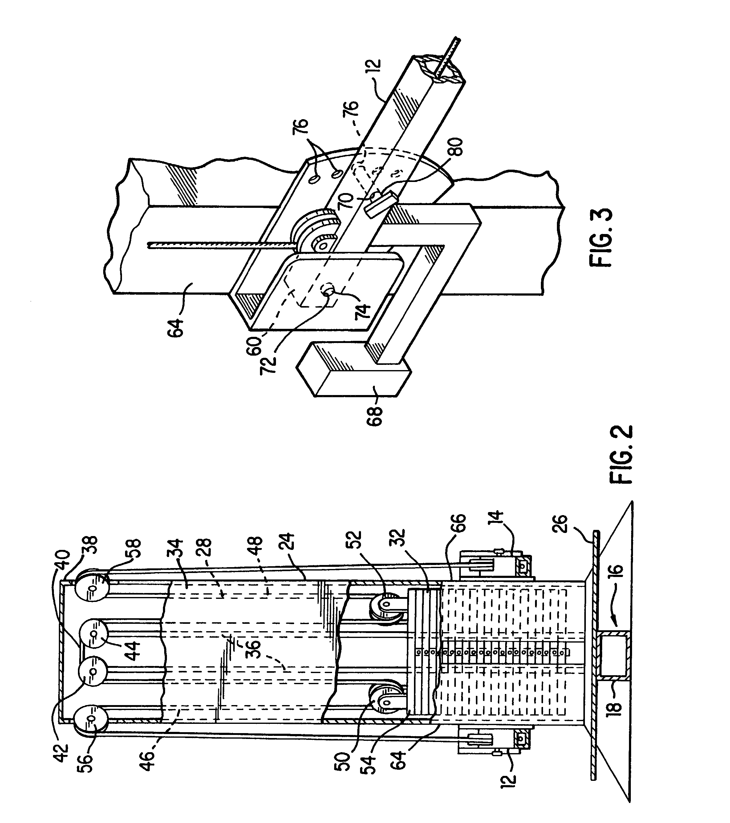
[0012]It is still a further object of the present invention to provide an exercise apparatus wherein the cable passes over a series of pulleys which create a 4:1 load ratio for each user handle.

Problems solved by technology

Unfortunately, the majority of these exercise apparatuses are large, cumbersome and difficult to utilize.
Such arrangements present significant limitations affecting the usefulness of the exercise apparatus.
In most instances, the effective useful length of the cable is limited by the height of the weight stack; that is, for each foot the cable is pulled by the user, the weight stack must rise a proportional distance.
Where the rise of the weight stack is substantially equal to the distance which the cable is pulled, the effective useful length of the cable is limited to only a few feet since building weight stacks any larger would be cost prohibitive, as well as structurally undesirable.
Weight stack based exercise apparatuses also encounter problems as a result of the momentum created when the weight plates are lifted under the control of a cable.
Such momentary changes are highly undesirable.

Method used


Image

  • Cable crossover exercise apparatus
  • Cable crossover exercise apparatus
  • Cable crossover exercise apparatus

Examples


Embodiment Construction

[0023]The detailed embodiments of the present invention are disclosed herein. It should be understood, however, that the disclosed embodiments are merely exemplary of the invention, which may be embodied in various forms. Therefore, the details disclosed herein are not to be interpreted as limited, but merely as the basis for the claims and as a basis for teaching one skilled in the art how to make and / or use the invention.

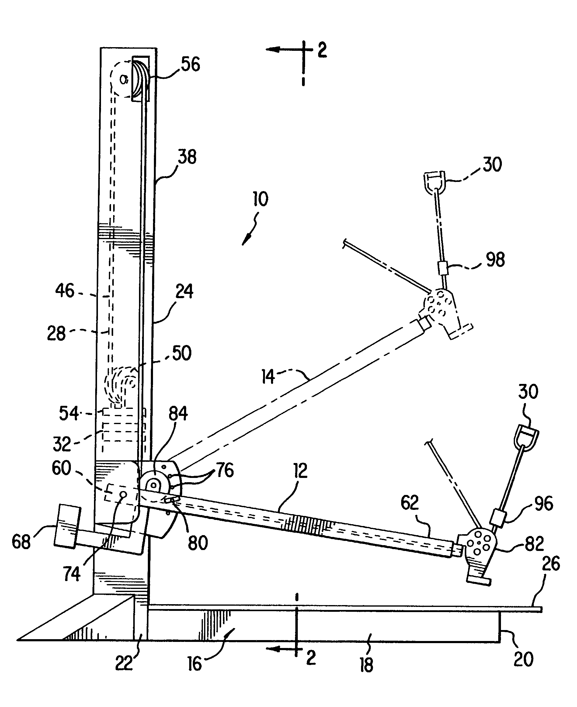
[0024]With reference to FIGS. 1 to 3, a functional lift exercise apparatuses 10 is disclosed. The functional lift exercise apparatus 10 includes a pair of parallel extension arms 12, 14 positioned to facilitate a wide range of lifting type exercises.

[0025]The functional lift exercise apparatus 10 further includes a base structure 16 having a central user support member 18 with a free first end 20 and a second end 22 to which a weight stack 24 is secured. Between the first end 20 and the second end 22, the central user support member 18 includes a platform 26 sized...


PUM


Abstract

A highly versatile exercise apparatuses is disclosed. More particularly, the invention relates to a cable crossover exercise apparatus including a central weight stack and opposed extension arms. The invention also relates to a functional lift exercise apparatus including a central weight stack and substantially parallel extension arms. The invention further relates to a cable type exercise apparatus employing a pulley assembly with a 4:1 load ratio.

Description

[0001]This patent application is a continuation of U.S. patent application Ser. No. 09 / 864,246 filed on May 25, 2001, entitled “Cable Crossover Exercise Apparatus,” inventor Roy Simonson, which has been assigned U.S. Pat. No. 6,458,061, and which is a continuation of U.S. patent application Ser. No. 09 / 395,194, filed on Sep. 14, 1999, entitled “Cable Crossover Exercise Apparatus,” now U.S. Pat. No. 6,238,323, each of which are incorporated herein in their entirety by reference.BACKGROUND OF THE INVENTION[0002]1. Field of the Invention[0003]The invention relates to highly versatile exercise apparatuses. More particularly, the invention relates to a cable crossover exercise apparatus including a central weight stack and opposed extension arms. The invention also relates to a functional lift exercise apparatus including a central weight stack and substantially parallel extension arms. The invention further relates to a cable type exercise apparatus employing a pulley assembly with a 4:...

Claims


Application Information

Patent Timeline
IPC IPC(8): A63B21/062A63B21/075
CPCA63B21/156A63B21/062A63B21/0628
Inventor SIMONSON, ROY
Owner ICON HEALTH & FITNESS INC
Learn More