
Optical-characteristic measurement apparatus and fundus-image observation apparatus

a measurement apparatus and optical character technology, applied in the field of optical character and fundus image observation apparatus, can solve the problems of unsuitable apparatuses, unfundamentally settled issues, burden on the person, etc., and achieve the effect of stable wavefront compensation

Inactive Publication Date: 2007-10-16
KK TOPCON
View PDF11 Cites 20 Cited by
  • Summary
  • Abstract
  • Description
  • Claims
  • Application Information

AI Technical Summary

Benefits of technology

[0008]Accordingly, it is an object of the present invention to provide an optical-characteristic measurement apparatus for measuring an optical characteristic and an fundus-image observation apparatus for forming an fundus-image by performing stable wavefront compensation even if an eye under measurement moves.
[0032]According to the present invention, an optical-characteristic measurement apparatus for measuring an optical characteristic and an fundus-image observation apparatus for forming an fundus-image both by performing stable wavefront compensation even if an eye under measurement moves, are provided.

Problems solved by technology

In adaptive optics, one of issues raised when a wavefront compensation device is used in order to compensate for aberrations of a human eye is the positional movement of the eye.
This method imposes a burden on the person, and does not fundamentally settle the issue of how to fix the position of the eye.
Hei-9-94230, the apparatuses are not suited, for example, to a case where a high magnification is used.

Method used


Image

  • Optical-characteristic measurement apparatus and fundus-image observation apparatus
  • Optical-characteristic measurement apparatus and fundus-image observation apparatus
  • Optical-characteristic measurement apparatus and fundus-image observation apparatus

Examples


Embodiment Construction

[0052]Embodiments of the present invention will be described below by referring to the drawings.

1. Hardware Structure

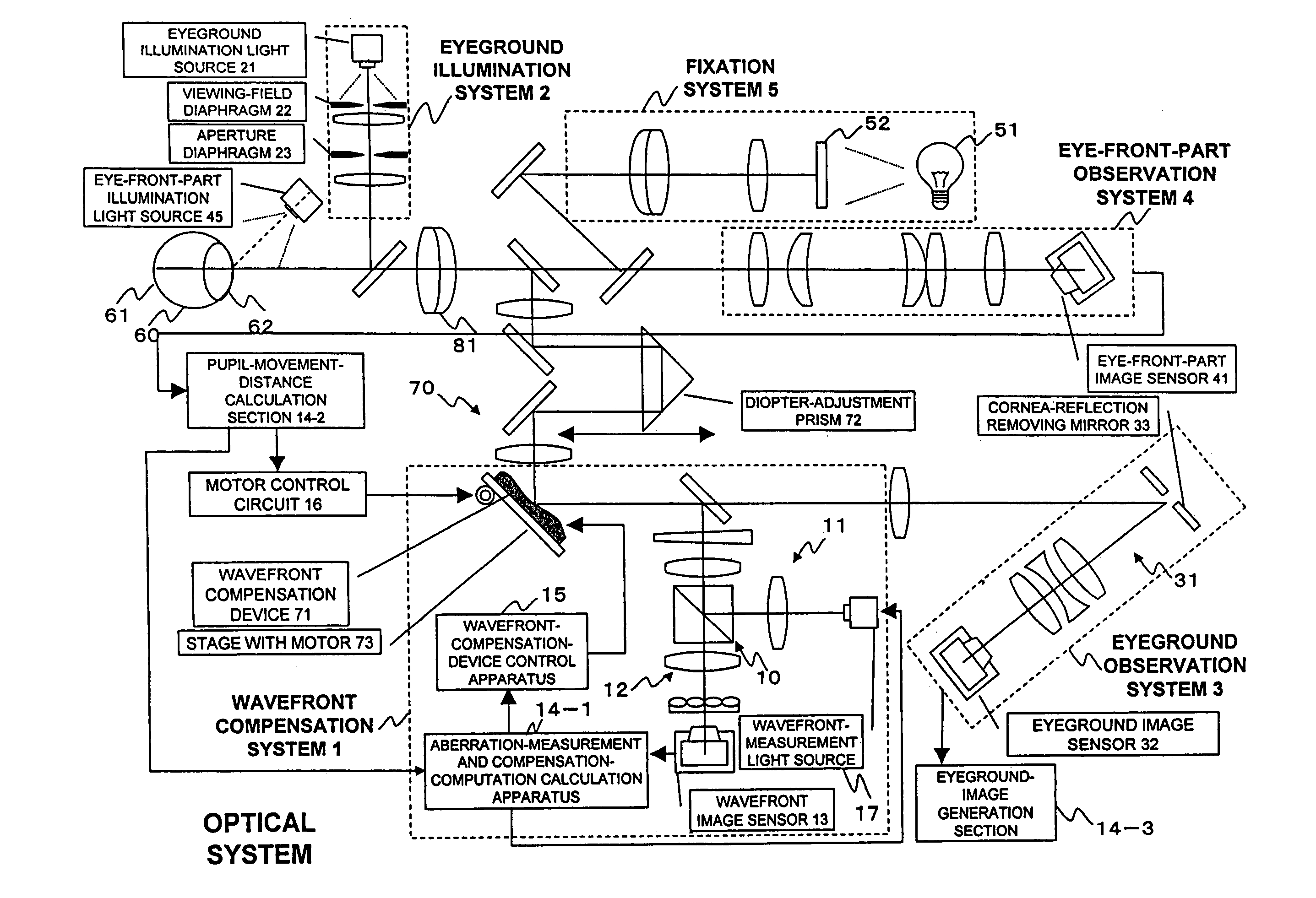
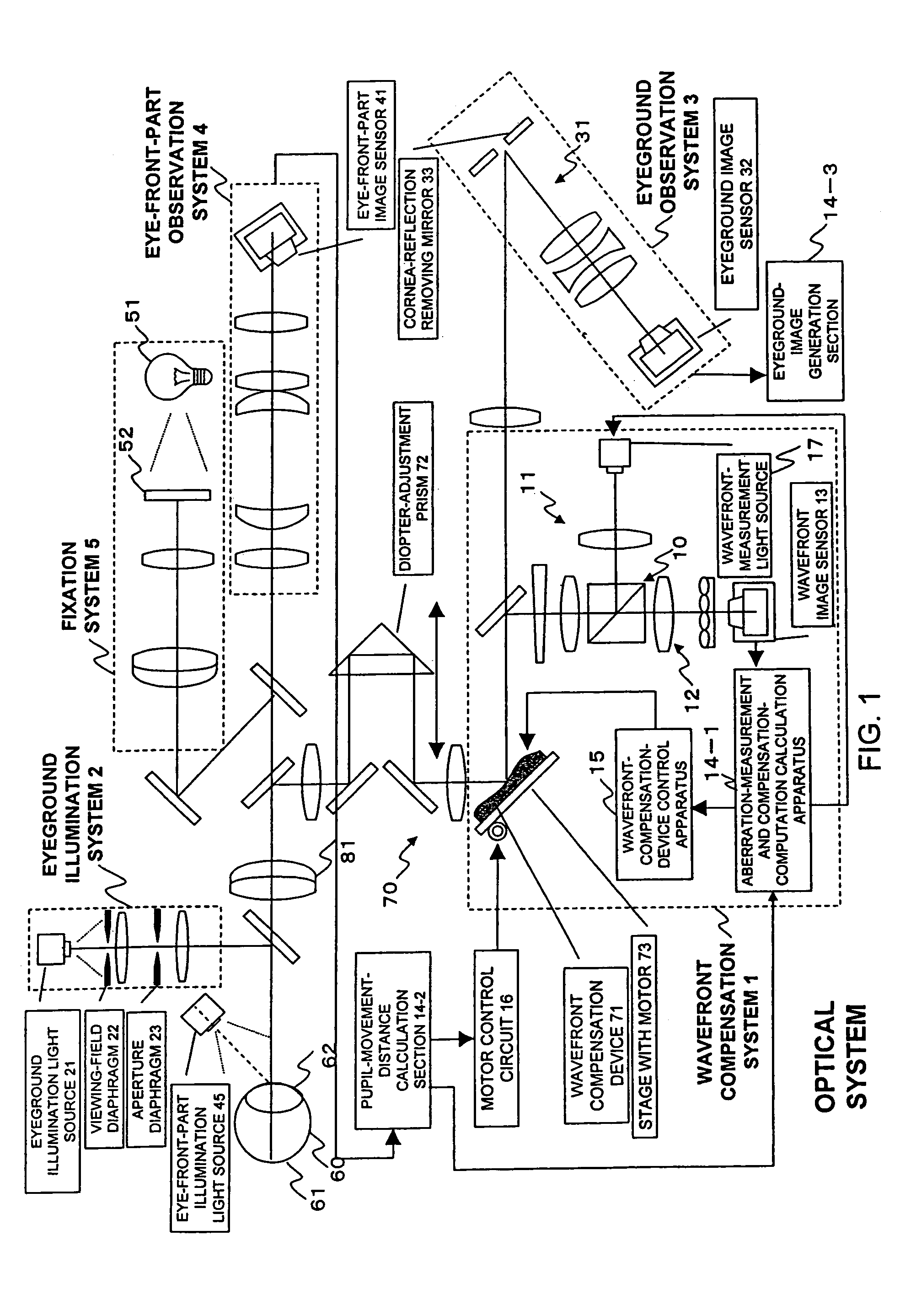
[0053]FIG. 1 is a view showing the structure of an eyeground observation apparatus. The eyeground observation apparatus includes a wavefront compensation system 1, an eyeground illumination system 2, an eyeground observation system 3, an eye-anterior-part observation system 4, an eye-anterior-part illumination light source 45, a fixation system 5, a compensation optical section 70, a motor control circuit 16, a pupil-movement-distance calculation section 14-2, and an fundus-image generation section 14-3.

[0054]The wavefront compensation system 1 includes a first illumination optical system 11, a first light-receiving optical system 12, a wavefront measurement system 10 having a second light-receiving section 13, an aberration-measurement and compensation-computation calculation apparatus (aberration calculation section, hereinafter called a calculation apparatus) 14-1,...


PUM


Abstract

An eye-anterior-part observation system receives light reflected from an eye anterior part of the eye under measurement illuminated by an eye-anterior-part illumination light source. A movement-distance calculation section measures the displacement of the eye from an eye anterior image by the eye-anterior-part observation system. A wavefront compensation device compensates the wavefront of light reflected or transmitted. A wavefront-measurement section projects light on the eyeground, and receives light reflected from the eyeground through the wavefront compensation device. A calculation apparatus measures wavefront aberrations, based on the measured displacement of the eye and a light-receiving signal by the wavefront-measurement section. A wavefront-compensation-device control apparatus generates a control signal based on the wavefront aberration, and outputs to the wavefront compensation device to compensate the wavefront. A stage with a motor moves the wavefront compensation device in a direction transversing the optical axis of the reflected light, based on the displacement of the eye.

Description

BACKGROUND OF THE INVENTION[0001]1. Field of the Invention[0002]The present invention relates to optical-characteristic measurement apparatuses and fundus-image observation apparatuses, and more particularly, to an optical-characteristic measurement apparatus and fundus-image observation apparatus for obtaining an optical characteristic and fundus-image of an eye under measurement, respectively, by compensating a wavefront by a wavefront compensation device.[0003]2. Description of the Related Art[0004]Recently, optical instruments used in the medical field have been spread. Especially in ophthalmology, optical-characteristic measurement apparatuses for checking eye functions such as the refraction and adjustment of eyes and the insides of eyeballs have been spread. For example, there exists a photorefractometer for obtaining the refractive degree and the corneal shape of an eye under measurement. In a conventional eyeground observation, an eyeground was observed with adjustment perf...

Claims


Application Information

Patent Timeline
Patent Type & Authority Patents(United States)
IPC IPC(8): A61B3/10A61B3/113A61B3/12
CPCA61B3/14
Inventor YAMAGUCHI, TATSUOMIHASHI, TOSHIFUMI
Owner KK TOPCON
Learn More