System and method for communicating packets in a network environment

Active Publication Date: 2007-10-09
CISCO TECH INC
View PDF7 Cites 1 Cited by
  • Summary
  • Abstract
  • Description
  • Claims
  • Application Information

AI Technical Summary

Benefits of technology

[0004]From the foregoing, it may be appreciated by those skilled in the art that a need has arisen for an improved communications approach that provides for increased authenticity and / or enhanced integrity in packet communications in a network environment. In accordance with one embodiment of the present invention, a system and method for communicating packets in a network environment are provided that greatly reduce disadvantages and problems associated with conventional packet communication techniques.
[0006]Certain embodiments of the present invention may provide a number of technical advantages. For example, according to one embodiment of the present invention, a communications approach is provided that allows for more secure communications between two points or network nodes. This is a result of a redundant packet, which may also be referred to as a confirmation packet, that may be exchanged between two network elements. The use of a redundant packet implies, to a receiving node, that a proper communication is being effectuated. Accordingly, if a receiving node receives a redundant packet within a given time interval, which is user-configurable, the receiving node is assured that the proffered identity of the communicating network element is valid and / or accurate.
[0007]Another technical advantage associated with one embodiment of the present invention is a result of filtering elements that may be used in conjunction with network elements. The filtering elements may perform front-end operations for the corresponding network element such that erroneous packets do not reach the intended destination of a receiving network element. This further simplifies communications between two network elements and reduces time-intensive operations associated with determining which packets are valid and which should be discarded. Thus, a filtering element can readily discard packets before an extensive examination of the packets is conducted by a receiving network element. As certain network designers and system operators may appreciate, this provides an approach that conserves network resources because problematic communications are being identified more quickly and without further burdening corresponding network elements. Moreover, the protocol for identifying and discarding erroneous packets may be executed quickly and easily without inhibiting existing network operations or other communication sessions being conducted. Certain embodiments of the present invention may enjoy some, all, or none of these advantages. Other technical advantages may be readily apparent to one skilled in the art from the following figures, description, and claims.

Problems solved by technology

Networking architectures have grown increasingly complex in communication environments.
In addition, the augmentation of clients or end users wishing to communicate in a network has caused many networking configurations and systems to become susceptible to elements that seek to misrepresent identities or corrupt network traffic.
This may create a security concern or an integrity issue because packet spoofing may be occurring in the network.

Method used


Image

  • System and method for communicating packets in a network environment
  • System and method for communicating packets in a network environment
  • System and method for communicating packets in a network environment

Examples


Embodiment Construction

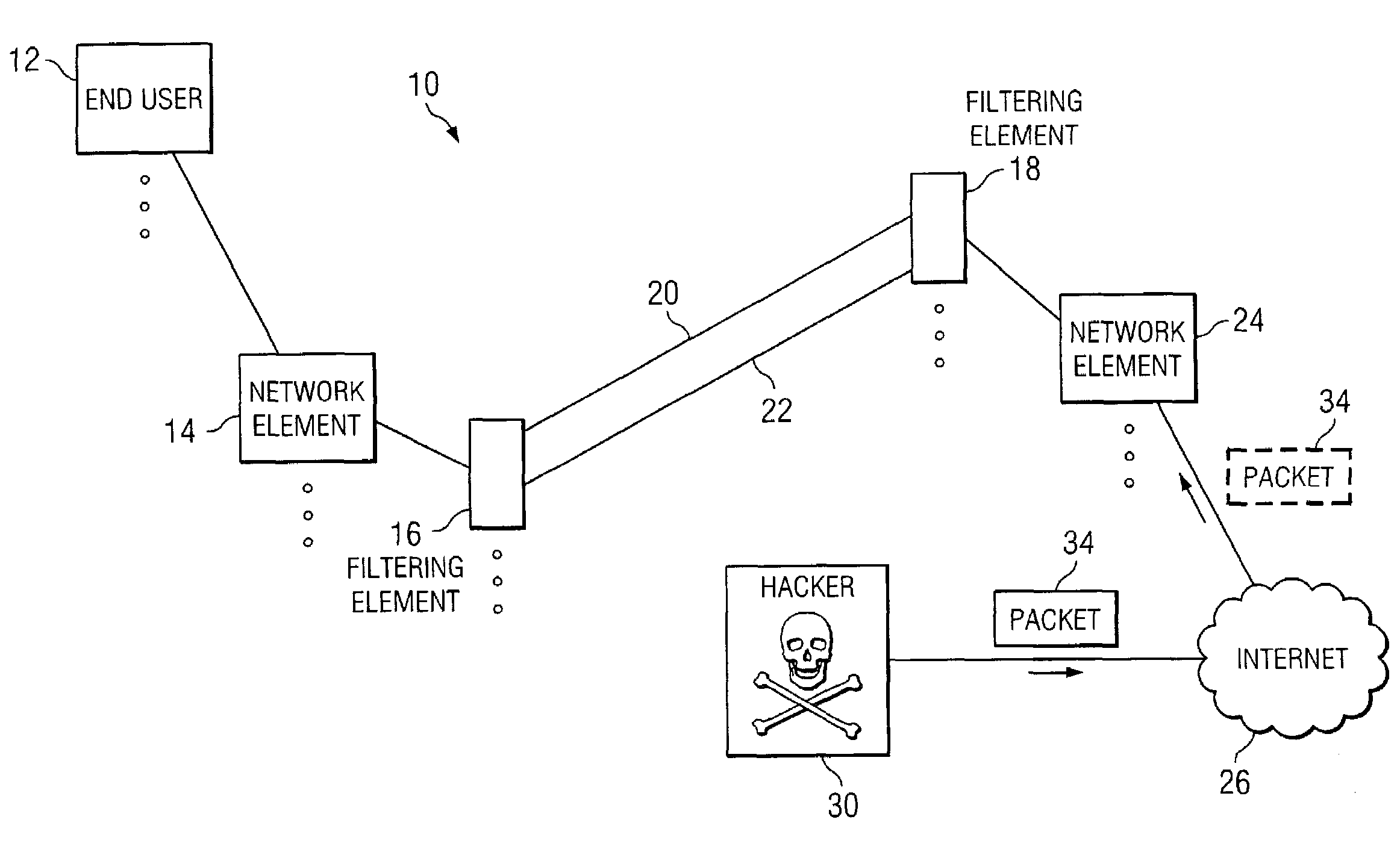
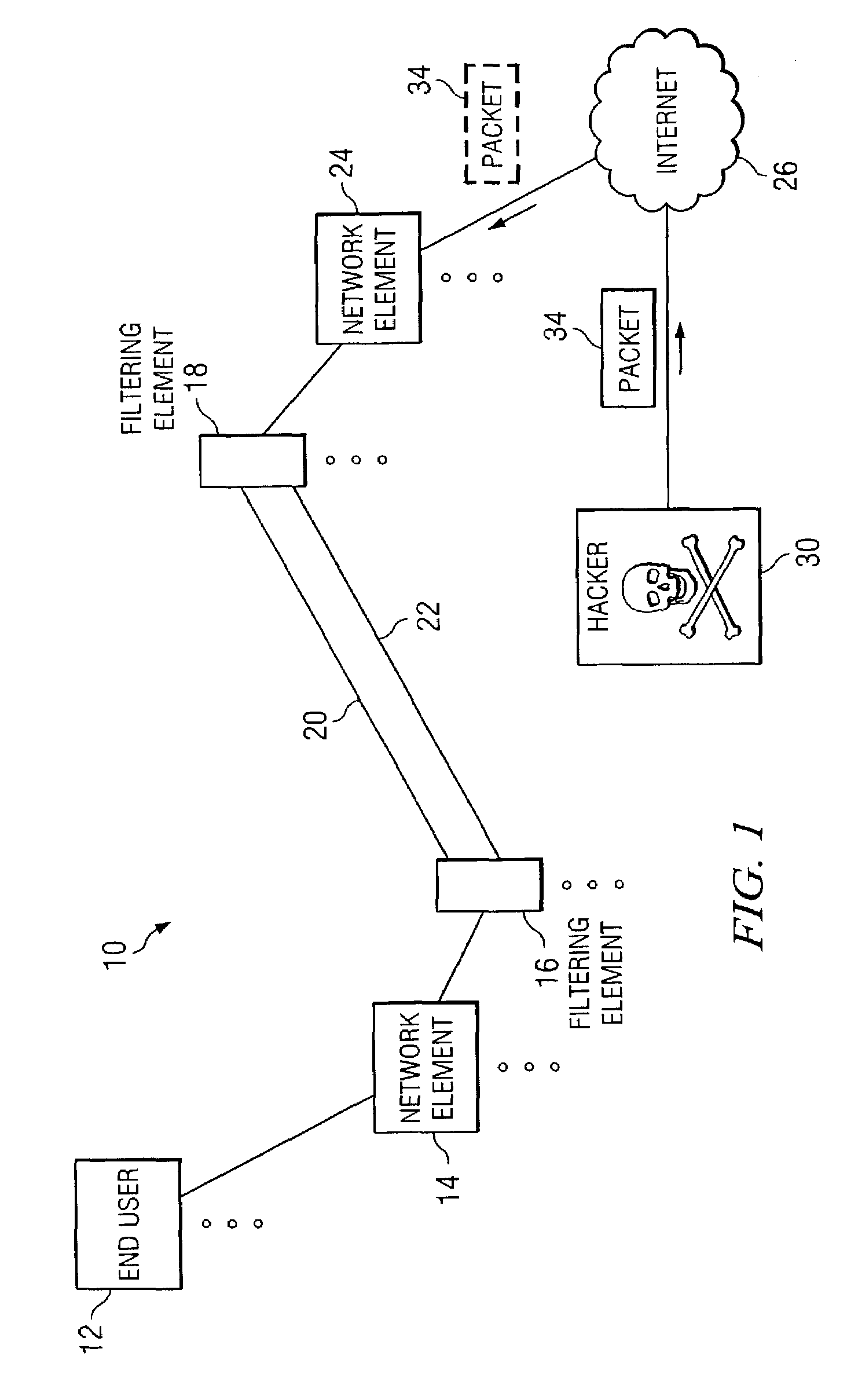
[0011]FIG. 1 is a simplified block diagram of a communication system 10 for communicating data or information in a network environment. Communication system 10 may include an end user 12, multiple network elements 14 and 24, multiple filtering elements 16 and 18, and an Internet 26. Filtering elements 16 and 18 may be coupled to each other via a set of communication links 20 and 22. In addition, communication system 10 may include a hacker 30 who may be attempting to send an erroneous packet 34 (or misrepresent the origin of packet 34) through Internet 26 and to network element 14. FIG. 1 may be generally configured or arranged to represent any communication architecture capable of exchanging packets in a network environment. In addition, communication system 10 may include any suitable networking protocol or arrangement that provides a communicative platform for communication system 10. Such architectures may include, for example, first generation, 2G, and 3G architectures that pro...


PUM


Abstract

A method for communicating packets in a network environment is provided that includes receiving a first and a second packet and determining if the second packet is substantially similar to the first packet. If the second packet is received during a predetermined time interval, then the first packet may be communicated to a next destination.

Description

TECHNICAL FIELD OF THE INVENTION[0001]This invention relates in general to the field of communications and more particularly to a system and method for communicating packets in a network environment.BACKGROUND OF THE INVENTION[0002]Networking architectures have grown increasingly complex in communication environments. In addition, the augmentation of clients or end users wishing to communicate in a network has caused many networking configurations and systems to become susceptible to elements that seek to misrepresent identities or corrupt network traffic. In general, communication tunnels or links may be used in order to establish or to gain access to a network, whereby an end user or an object may initiate some protocol by invoking a selected location or a network node. As the subscriber base of end-users increases, proper routing of communication tunnels or links and efficient management of data flows becomes even more critical.[0003]As a packet traverses the network through a gi...

Claims


Application Information

Patent Timeline
IPC IPC(8): G06F7/04H04L9/00
CPCH04L63/1441H04L63/0236
Inventor GAGE, TIMOTHY M.RETANA, ALVARO E.
Owner CISCO TECH INC
Why Eureka
Try Eureka