
Large core holey fibers

a holey fiber and core technology, applied in the field of optical fibers, can solve the problems of peak intensities that induce non-linearities in the properties of the core and fiber, limited core dimension to a relatively small value, and inability to apply high-power fibers, so as to achieve the effect of being practical or not possibl

Active Publication Date: 2007-10-09
IMRA AMERICA
View PDF2 Cites 71 Cited by
  • Summary
  • Abstract
  • Description
  • Claims
  • Application Information

AI Technical Summary

Benefits of technology

The patent describes an optical fiber design that can propagate a single optical mode and suppress higher order modes. The fiber has a cladding region with multiple cladding features that provide an increased effective core size and substantial confinement of light within the core. The cladding features have an average spacing and size that yield a ratio of effective core size to the average spacing and size of the cladding features. The fiber also has a core region surrounded by the cladding region, which further enhances the confinement of the optical mode. The technical effect of this design is that it allows for better coupling of the optical mode to the fiber, resulting in improved laser and amplifier performance.

Problems solved by technology

One limitation of such single-mode traditional fibers and conventional PCFs is that the core dimension is limited to a relatively small value.
In such small core fibers, high optical power levels result in peak intensities that induce non-linearities in the properties of the core and fiber.
High power application of such fibers, therefore, is either not practical or not possible.

Method used


Image

  • Large core holey fibers
  • Large core holey fibers
  • Large core holey fibers

Examples


Embodiment Construction

[0088]These and other aspects, advantages, and novel features of the present teachings are apparent from the following detailed description and the accompanying drawings. In the drawings, similar elements have similar reference numerals.

[0089]The present teachings generally relate to holey fibers, photonic crystal fibers, and photonic bandgap fiber. For the purpose of description herein, and in accordance with current usage of terms of art, a holey fiber is an optical fiber where optical guidance is essentially provided by a regularly or irregularly arranged cladding features or “holes.” As used herein, holes refers to features disposed in a matrix material having different optical properties such as index of refraction in comparison to the matrix material. The holes can be open, evacuated, or filled with air, gas, liquid, or may comprise other material, transparent or non-transparent, such as for example glass, polymer, or other substance or material. A photonic crystal fiber (PCF)...


PUM


Abstract

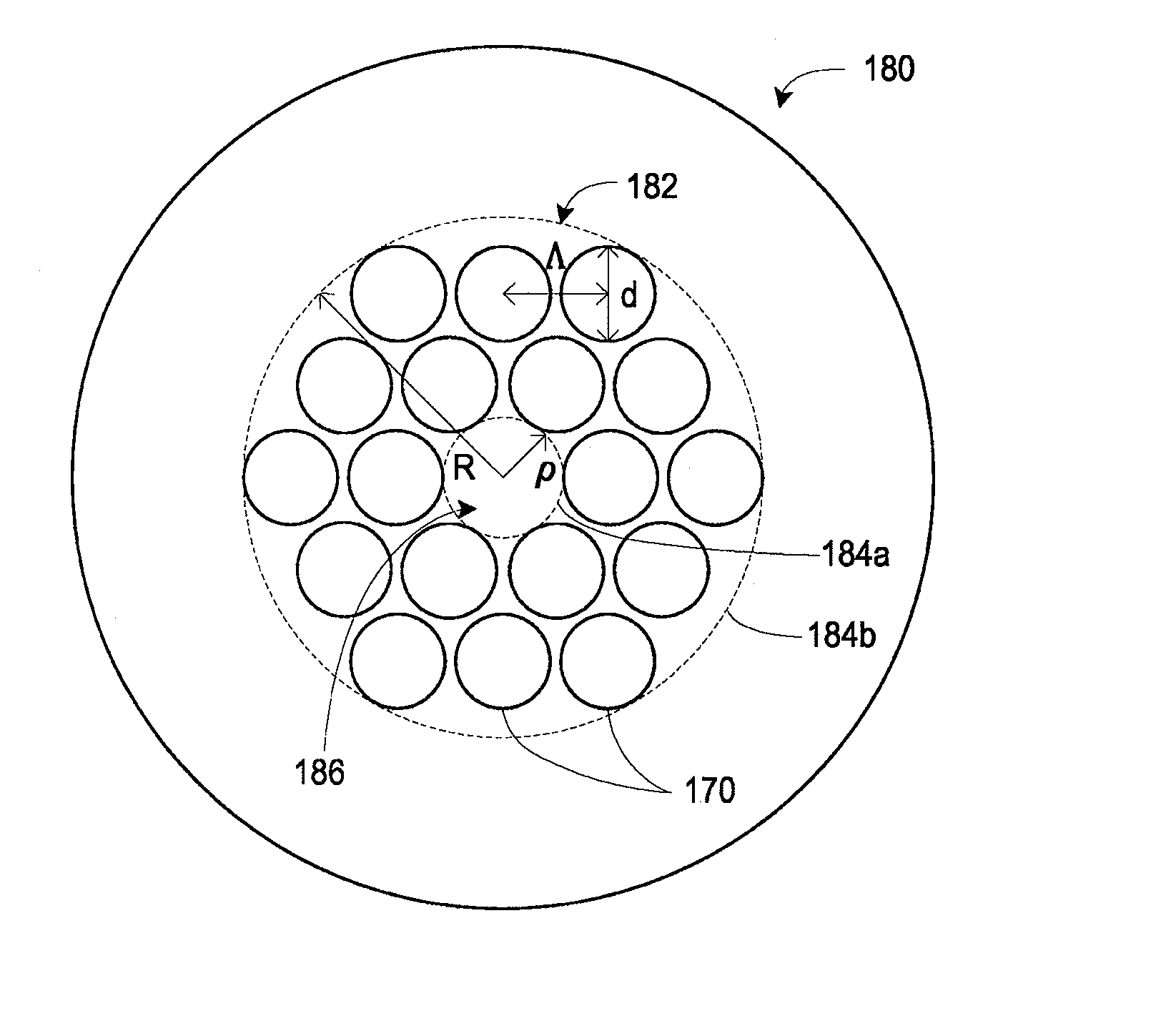
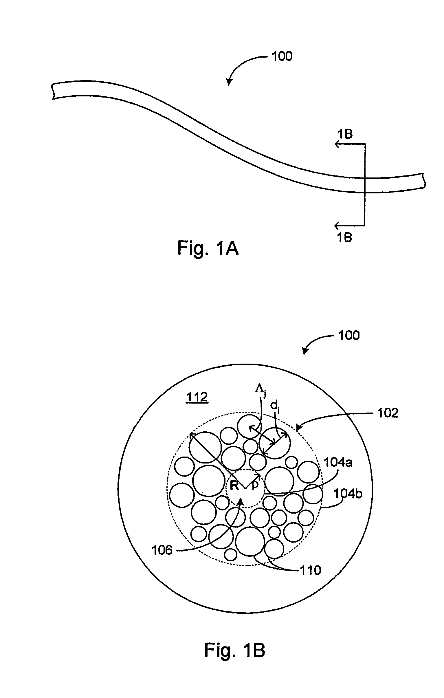
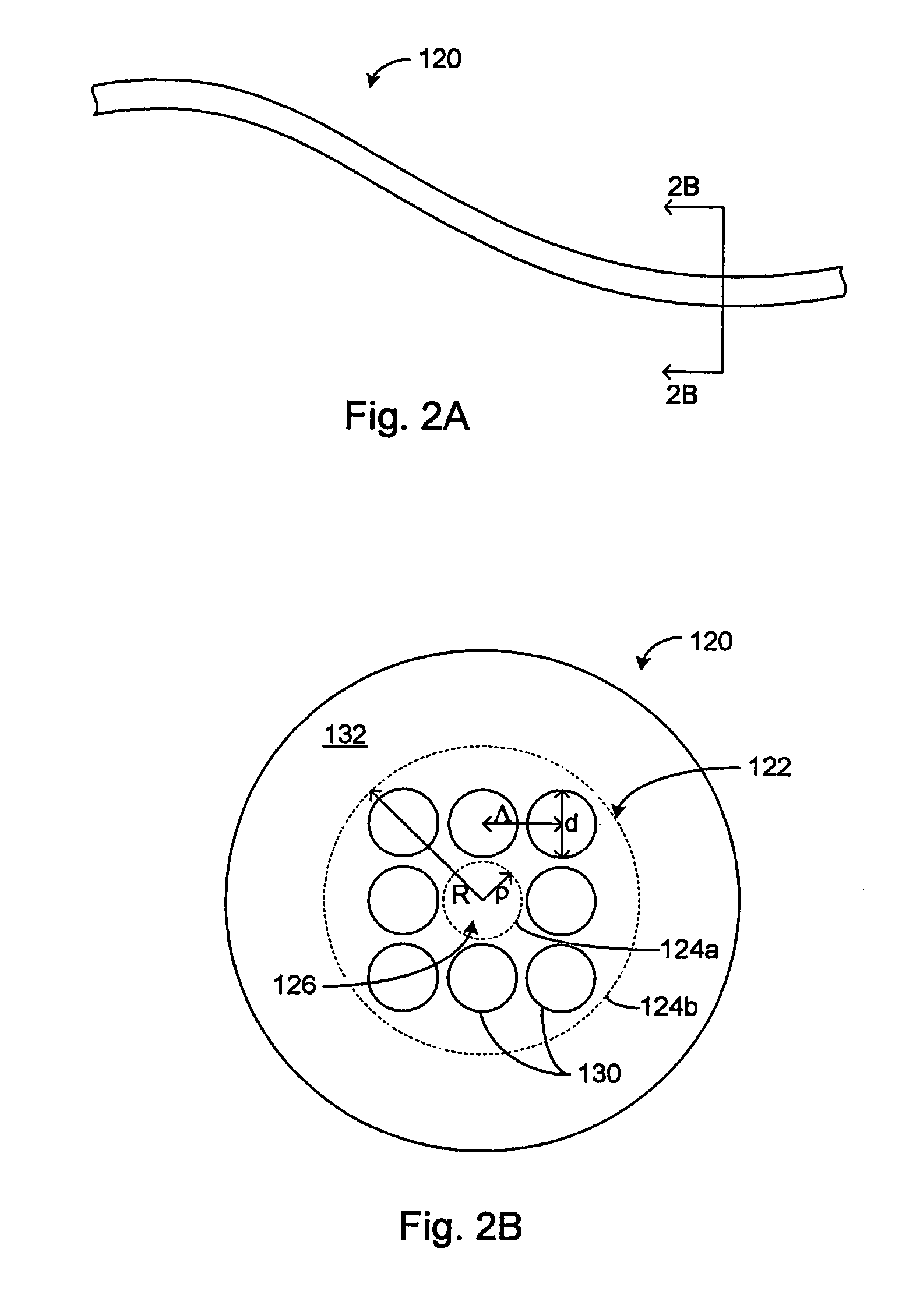
Various types of holey fiber provide optical propagation. In various embodiments, for example, a large core holey fiber comprises a cladding region formed by large holes arranged in few layers. The number of layers or rows of holes about the large core can be used to coarse tune the leakage losses of the fundamental and higher modes of a signal, thereby allowing the non-fundamental modes to be substantially eliminated by leakage over a given length of fiber. Fine tuning of leakage losses can be performed by adjusting the hole dimension and / or the hole spacing to yield a desired operation with a desired leakage loss of the fundamental mode. Resulting holey fibers have a large hole dimension and spacing, and thus a large core, when compared to traditional fibers and conventional fibers that propagate a single mode. Other loss mechanisms, such as bend loss and modal spacing can be utilized for selected modes of operation of holey fibers. Other embodiments are also provided.

Description

PRIORITY APPLICATION [0001]This application claims the benefit of U.S. provisional application 60 / 536,914 filed Jan. 16, 2004 entitled “LARGE CORE HOLEY FIBERS” which is incorporated herein by reference in its entirety.BACKGROUND [0002]1. Field[0003]The present teachings relate to optical fibers in general and in particular, to single-mode and multi-mode holey fibers having large core dimensions and devices and systems that use such fibers such as lasers and amplifiers.[0004]2. Description of the Related Art[0005]A holey fiber is an optical fiber where optical guidance is provided by an arrangement of “holes” disposed about a core. Such holes may have a refractive index lower than that of the core, and collectively form a cladding region having an effective refractive index also lower than that of the core.[0006]More generally, holey fiber is used herein to refer to fiber comprising a plurality of cladding features, e.g., holes, disposed in a matrix, wherein the cladding features ma...

Claims


Application Information

Patent Timeline
Patent Type & Authority Patents(United States)
IPC IPC(8): G02B6/02G02B6/26G02B6/14
CPCG02B6/02009H01S3/06754G02B6/02338G02B6/02357G02B6/02361G02B6/02366G02B6/14G02B6/02342H01S3/06741G02B6/02047G02B6/024G02B6/032G02B6/32H01S3/06729G02B6/02328H01S3/06716H01S3/06733
Inventor DONG, LIANGHARTER, DONALD J.WONG, WILLIAM
Owner IMRA AMERICA
Learn More