
Optical recording/reproducing medium, stamper for manufacturing optical recording/reproducing medium, and optical recording/reproducing apparatus

a technology of optical recording/reproducing medium and optical recording/reproducing apparatus, which is applied in the direction of recording information storage, instrumentation, disposition/mounting of heads, etc., can solve the problems of insufficient recording/reproduction characteristics, and achieve the effect of stably reproducing groove signals, and reducing the modulation degr

Inactive Publication Date: 2007-10-09
SONY CORP
View PDF10 Cites 13 Cited by
  • Summary
  • Abstract
  • Description
  • Claims
  • Application Information

AI Technical Summary

Benefits of technology

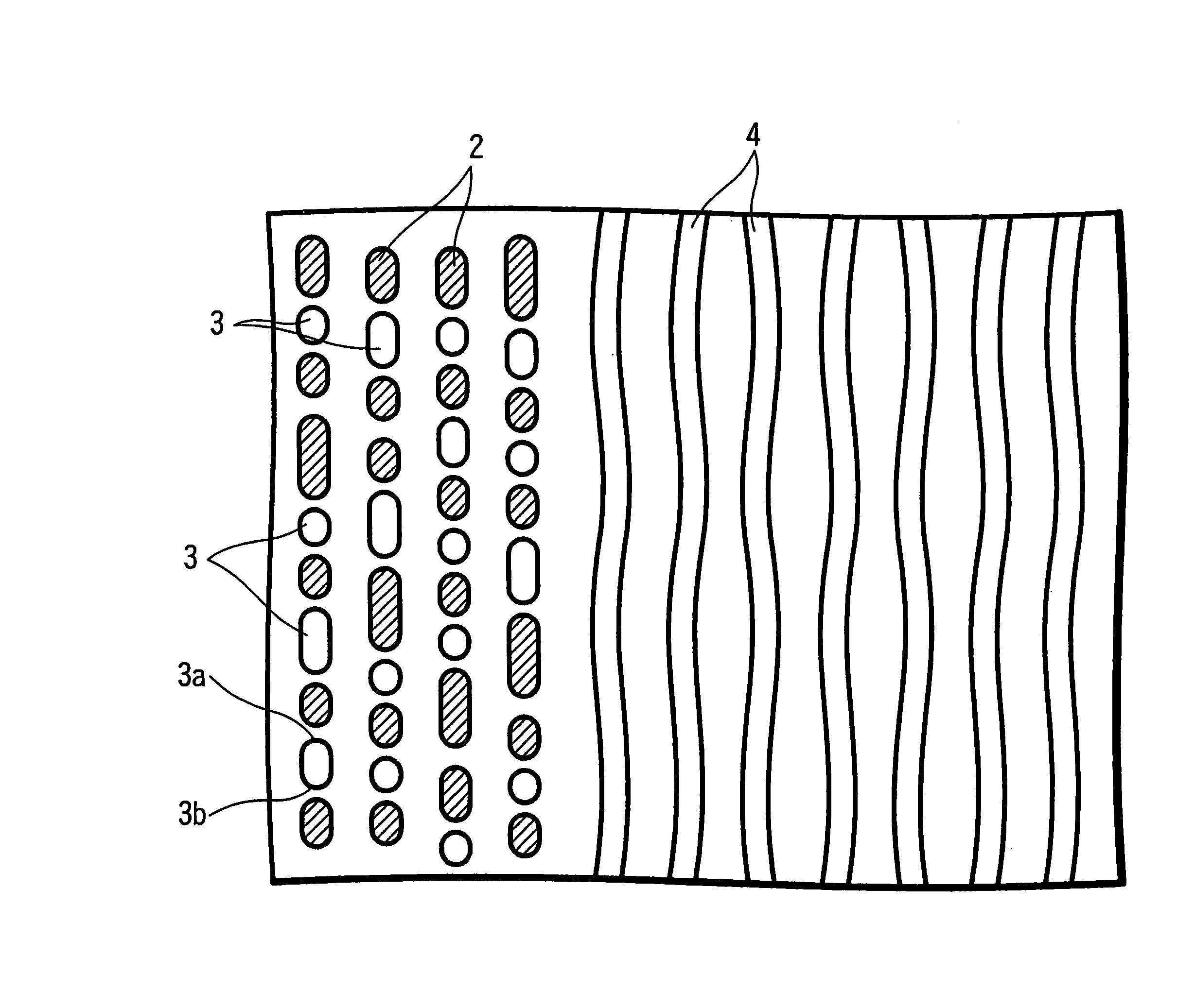
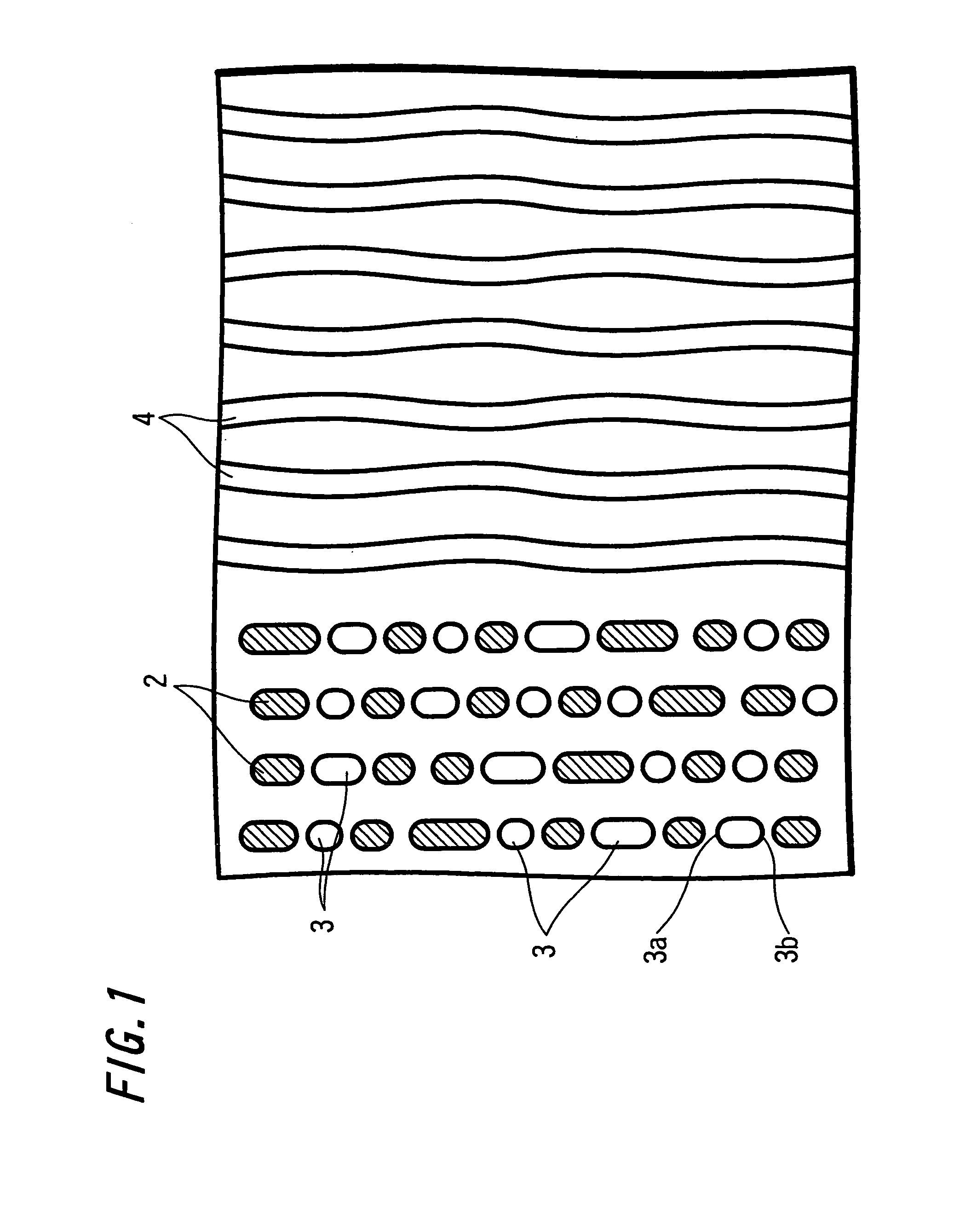
[0056]As described above, according to the present invention, since auxiliary pits are formed in at least a portion of the spaces between adjacent pits along the recording track direction, with a depth equal to or less than the pit depth, and with both edges of the auxiliary pits along the recording track direction shaped as simple convex curves, the pit density, that is, the pit duty in the recording track direction, that is, in the circumferential direction of a disc-shaped medium can be increased to more than 50%, and the push-pull signal amplitude can be increased.
[0064]Furthermore, even when the groove track pitch is reduced to be equal to or greater than 4 / 3 of, but less than 3 / 2 of, the track pitch of the cutoff frequency in order to increase the density, according to the present invention as described above, pit signals can be stably reproduced; hence the same track pitch can be used for pits and grooves, and the same modulation method can be used for pits and grooves, so that inconveniences such as the use of a separate format solely for pit portions can be avoided.

Problems solved by technology

However, if an attempt is made to similarly set the pit signal depth, there is a problem that sufficient recording / reproduction characteristics are not obtained for the signals of comparatively shallow pits with a phase depth of approximately λ / 16n≦x≦λ / 12n, that is, in one example, inserting λ=406 nm and n=1.48, a depth of approximately 17 to 23 nm.

Method used


Image

  • Optical recording/reproducing medium, stamper for manufacturing optical recording/reproducing medium, and optical recording/reproducing apparatus
  • Optical recording/reproducing medium, stamper for manufacturing optical recording/reproducing medium, and optical recording/reproducing apparatus
  • Optical recording/reproducing medium, stamper for manufacturing optical recording/reproducing medium, and optical recording/reproducing apparatus

Examples


embodiment

[0129]Next, evaluations of the depression / protrusion pattern reproduction characteristics were performed for the optical recording / reproduction medium having the above-described configuration of this invention, and, as a comparative example, for an optical recording / reproduction medium without auxiliary pits provided, using an optical recording / reproducing device comprising the optical system described in FIG. 6 above, with wavelength λ=406 nm and numerical aperture NA=0.85. As explained above, the track pitch was set to 0.32 μm.

[0130]In the modulation optical system OM1 of the optical recording device as explained above using FIG. 4, the exposure power was adjusted for pits and for auxiliary pits, and examples of respective optical recording / reproduction media were manufactured having pits and auxiliary pits with different depths.

[0131]Discs A through E were fabricated, with pit depths of 47 nm, 39 nm, 34 nm, 23 nm, and 21 nm respectively; regions were formed on each disc in which ...


PUM

PropertyMeasurementUnit
wavelengthaaaaaaaaaa
light wavelengthaaaaaaaaaa
phase depthaaaaaaaaaa

Abstract

An optical recording and reproduction medium in which pits corresponding to recording information are formed along a recording track, wherein auxiliary pits are formed in at least a portion of the spaces between adjacent pits along the recording track direction; when the pit depth is d1 and the auxiliary pit depth is d2, then d1≧d2 is obtained; and both edges of the auxiliary pits along the recording track direction are shaped as simple convex curves.

Description

TECHNICAL FIELD[0001]This invention relates to an optical recording and reproduction medium in which pits corresponding to recorded information are formed along recording tracks, a stamper for manufacturing the optical recording and reproduction medium, and an optical recording and reproducing device.BACKGROUND ART[0002]Various optical discs, formed in a disc shape and onto which optical recording and / or reproduction are performed, are currently in use as optical recording / reproduction media. Such optical discs include read-only optical discs, in which embossed pits corresponding to data are formed in advance in the disc substrate; magneto-optical discs, which utilize a magneto-optical effect to perform data recording; and phase-change optical discs, which use phase changes in the recording film to perform data recording.[0003]Of these discs, in optical discs enabling writing, such as magneto-optical discs and phase-change optical discs, grooves are conventionally formed in the disc...

Claims


Application Information

Patent Timeline
Patent Type & Authority Patents(United States)
IPC IPC(8): G11B7/24G11B7/013G11B7/09G11B7/135G11B7/24085G11B7/26
CPCG11B7/0938G11B7/24G11B7/263G11B7/261G11B7/24085
Inventor ENDOH, SOHMEI
Owner SONY CORP
Learn More