
Visible light communication apparatus

a technology of communication apparatus and light source, applied in the field of visible light communication apparatus, can solve the problems of communication error and modulation degree decline, and achieve the effect of suppressing the reduction of modulation degr

Active Publication Date: 2017-01-24
PANASONIC INTELLECTUAL PROPERTY MANAGEMENT CO LTD
View PDF32 Cites 0 Cited by
  • Summary
  • Abstract
  • Description
  • Claims
  • Application Information

AI Technical Summary

Benefits of technology

[0006]In view of the above, the present disclosure provides a visible light communication apparatus capable of suppressing a reduction in modulation degree during dimming of light emitting elements.
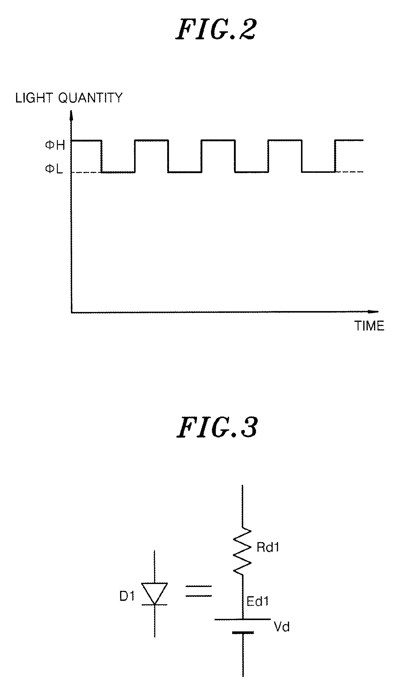
[0011]With the above configuration since both the resistance value of the equivalent resistance of the load circuit (light emitting elements) and the resistance value of the equivalent circuit of the load variation circuit increase when the load current decreases, there is an effect that it is possible to suppress a reduction in modulation degree during dimming of the light emitting elements.

Problems solved by technology

Therefore, during dimming of the light emitting diodes in which the current supplied to the light emitting diodes is small, there is a possibility that a modulation degree decreases and a communication error occurs.

Method used


Image

  • Visible light communication apparatus
  • Visible light communication apparatus
  • Visible light communication apparatus

Examples


embodiment

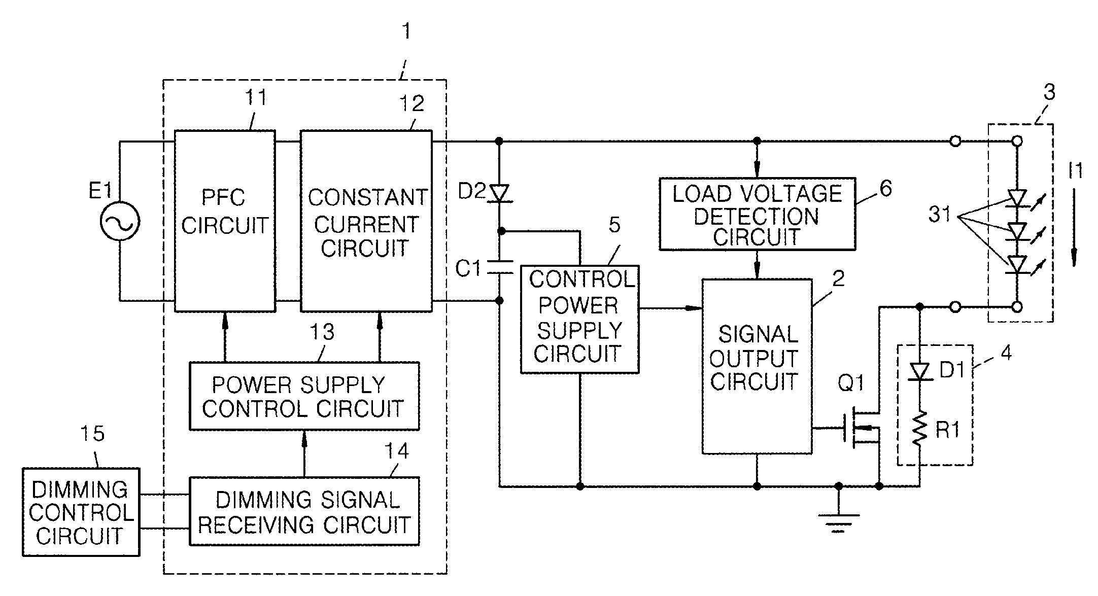
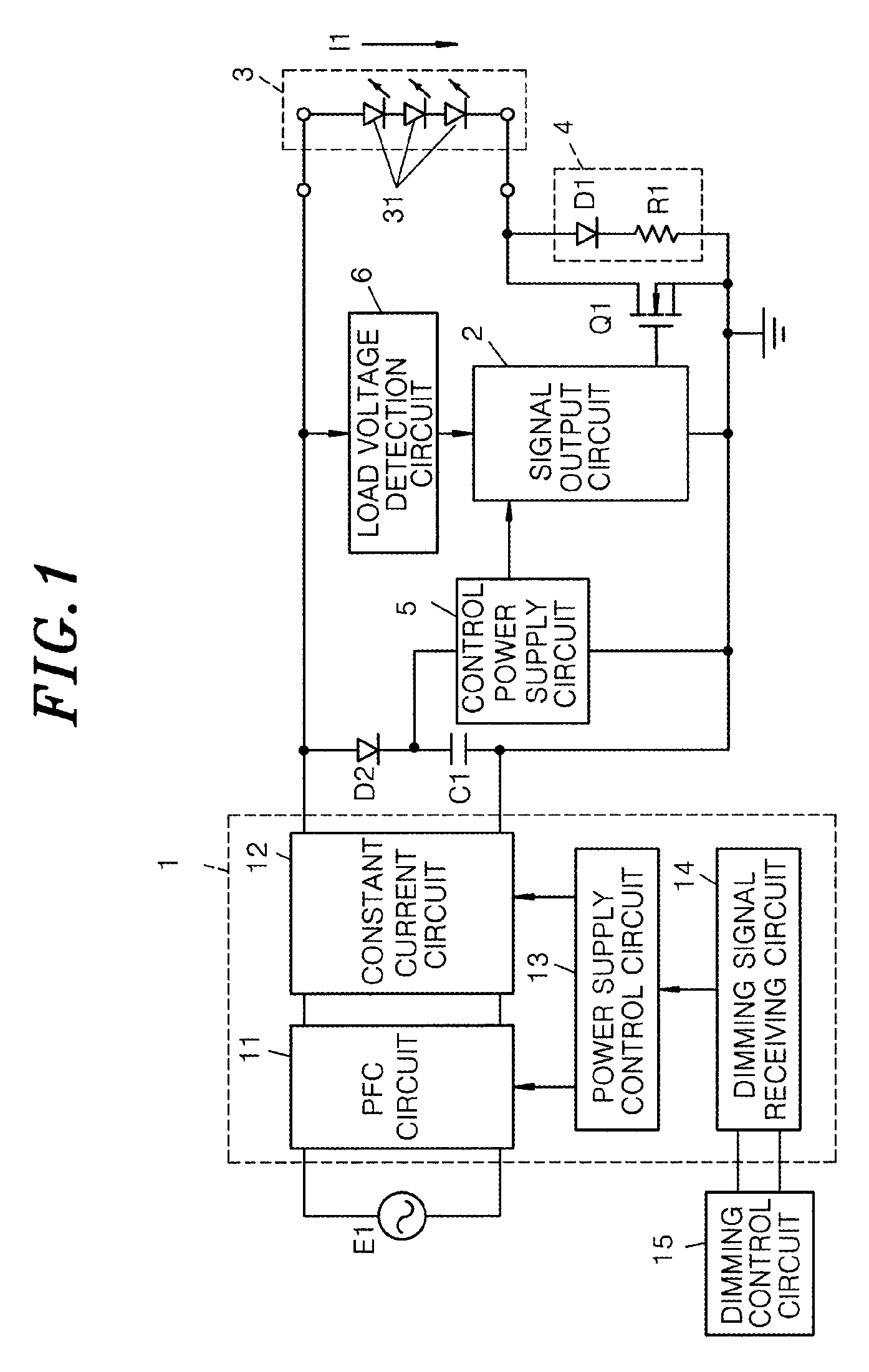
[0022]FIG. 1 shows an example of a circuit configuration of a visible light communication apparatus in accordance with the present embodiment. The visible light communication apparatus of the present embodiment mainly includes a power supply circuit 1, a signal output circuit 2, a load circuit 3, a load variation circuit 4, and a switching element Q1. The visible light communication apparatus transmits a signal by modulating illumination light of light emitting diodes 31 (light emitting elements) included in the load circuit 3. In the following, there will be described a configuration of the visible light communication apparatus of the present embodiment.

[0023]The load circuit 3 includes the light emitting diodes 31 connected in series, and functions as a light source.

[0024]The power supply circuit 1 receives an input power from a commercial power source E1 and supplies a load current I1 to the load circuit 3 (light emitting diodes 31). Specifically, the power supply circuit 1 inclu...


PUM


Abstract

A visible light communication apparatus includes a constant current circuit and a load circuit including light emitting elements connected to output terminals of the constant current circuit. Further, the visible light communication apparatus includes a load variation circuit configured to change load characteristics of the load circuit by electrically connecting to the load circuit, the load variation circuit including a series circuit of a diode and a resistor connected in series to the load circuit and a switching element configured to electrically connect or disconnect the load variation circuit to the load circuit in response to a binary communication signal.

Description

CROSS-REFERENCE TO RELATED APPLICATION[0001]This application claims priority to Japanese Patent Application No. 2013-210586 filed on Oct. 7, 2013, the entire contents of which are incorporated herein by reference.TECHNICAL FIELD[0002]The present disclosure relates to a visible light communication apparatus.BACKGROUND ART[0003]Conventionally, there is known a visible light communication apparatus (illumination apparatus) which includes light emitting diodes (LEDs) as a light source and transmits a signal by modulating the intensity of illumination light (see, e.g., Japanese Unexamined Patent Application Publication No. 2013-110634). In the visible light communication apparatus, since the signal is transmitted by modulating the illumination light itself, there is no need for a special device as in an infrared communication device. Further, since power saving can be achieved by using light emitting diodes as the light source, it is being studied to use the visible light communication a...

Claims


Application Information

Patent Timeline
Patent Type & Authority Patents(United States)
IPC IPC(8): H04B10/00H04J14/02H04B10/116H05B37/02H04B10/532H04B10/25
CPCH04B10/116H04B10/25H04B10/532H05B37/02H05B45/37H05B47/10H05B47/195
Inventor KIDO, SHOJIROUSHIOHAMA, EIJIMATSUKAWA, YOSHIHIKOIKEHARA, MASAAKI
Owner PANASONIC INTELLECTUAL PROPERTY MANAGEMENT CO LTD
Learn More