Method and device for detecting land pre-pits
- Summary
- Abstract
- Description
- Claims
- Application Information
AI Technical Summary
Benefits of technology
Problems solved by technology
Method used
Image
Examples
first embodiment
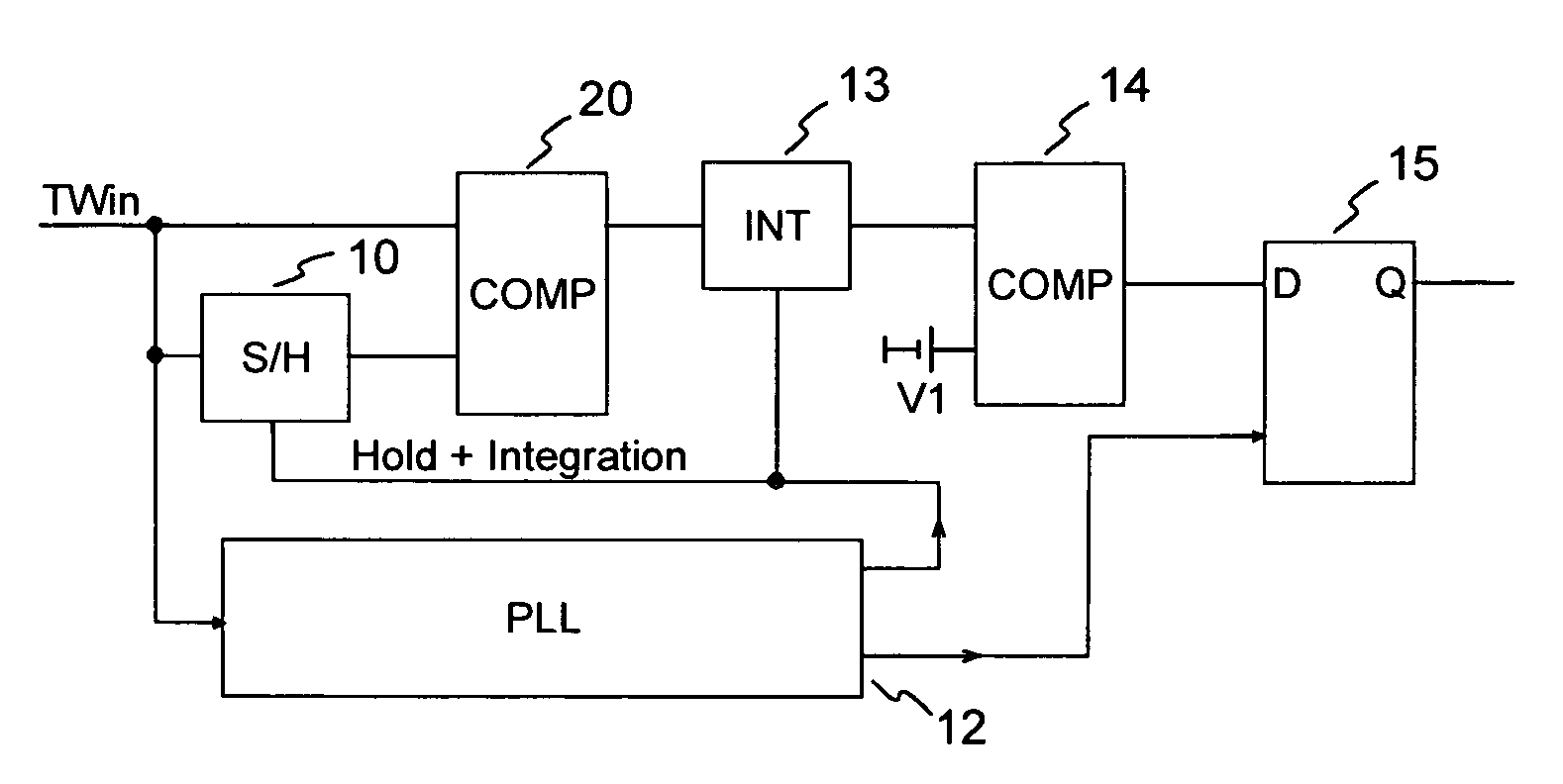
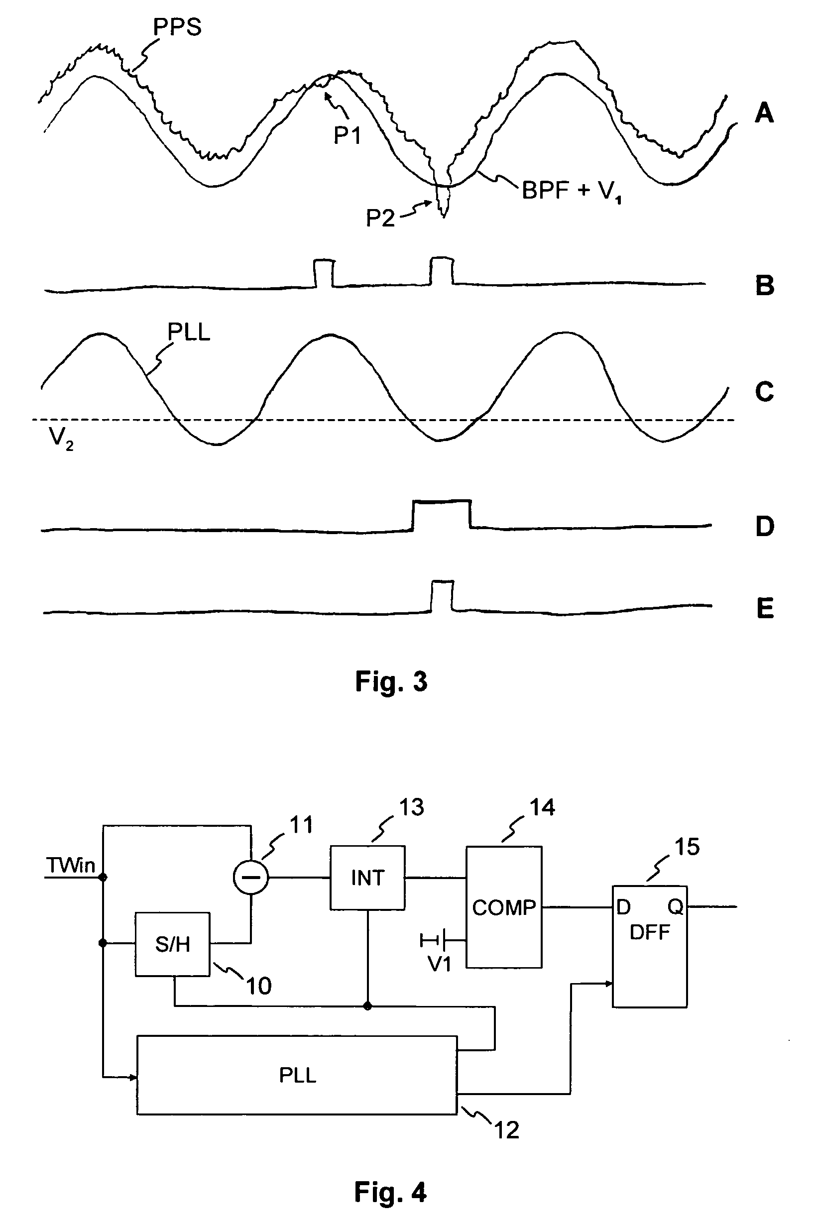
[0075]A first embodiment is illustrated in FIG. 21. Since the LPP signal occurs at particular positions of the track wobble signal (FIG. 21A) and has a particular tolerance with respect to this theoretical position, it is possible to control a sample / hold block by a window signal (S / H gate, FIG. 21D) so that a phase error signal distortion received by the signal of FIG. 21B is muted. For this purpose, the sample / hold block is controlled so as to maintain the voltage value of the TW signal during the expected occurrence of the LPP signal. Right after the expected end of the LPP the sample / hold block is deactivated again.
[0076]A first embodiment of a PLL 12 according to the invention is illustrated in FIG. 24. A sample / hold block 126 is connected in front of the phase detector 120. The sample / hold block can save the value of an input signal at the beginning of a time interval determined by a control signal (S / H gate, not shown) and can freeze this value until the end of the time inter...
second embodiment
[0079]A second embodiment for generating a phase error signal not being affected by LPP is shown in FIG. 26. Within the time interval in which the LPP occurs, the phase error signal is switched to zero. For this purpose, a switch 127 is inserted between phase detector output and loop filter 121. The resulting phase error signal is shown in FIG. 22E (analogous in FIG. 22C). Due to the muting, see FIG. 22D, of the faulty phase error signal during occurrence of the LPP the average value of the corrected phase error signal (FIG. 22E) remains zero. If necessary, the time interval in which the generation of the phase error signal is muted may be extended to the entire half wave of the track wobble Signal in which a LPP is situated (FIG. 23).
[0080]An alternative to the embodiment shown in FIG. 26 is, instead of the square-wave signal controlling the multiplication (+1; −1), to generate a signal which defines three factors (+1; 0; −1) for multiplication. The positions at which one of the fa...
PUM
| Property | Measurement | Unit |
|---|---|---|
| phase angle | aaaaa | aaaaa |
| phase angle | aaaaa | aaaaa |
| threshold | aaaaa | aaaaa |
Abstract
Description
Claims
Application Information
 - R&D
- Intellectual Property
- Life Sciences
- Materials
- Tech Scout
- Unparalleled Data Quality
- Higher Quality Content
- 60% Fewer Hallucinations
Browse by: Latest US Patents, China's latest patents, Technical Efficacy Thesaurus, Application Domain, Technology Topic, Popular Technical Reports.
© 2025 PatSnap. All rights reserved.Legal|Privacy policy|Modern Slavery Act Transparency Statement|Sitemap|About US| Contact US: help@patsnap.com


