
Method and apparatus for rendering large patterns in a small memory printer

a printer and memory technology, applied in the field of printing control, can solve the problems of large amount of memory required, poor quality, and inability to store large patterns in pattern caches at high resolution, and achieve the effects of shortening the software development of the printer, increasing user satisfaction with the printer, and increasing the complexity of the pag

Active Publication Date: 2007-10-09
TEXAS INSTR INC
View PDF7 Cites 2 Cited by
  • Summary
  • Abstract
  • Description
  • Claims
  • Application Information

AI Technical Summary

Benefits of technology

[0006]This method allows the printer to print more complex pages. This increases user satisfaction with the printer. Some pages that overflow the pattern cache in a prior art implementation and cause quality reducing reversion compress / decompress cycles will actually be rendered at full quality using this method. Employing the same set of rasterizing primitives for this pattern cache reduction and for rendering shortens the software development for the printer. Page pipelining is enhanced by decoupling the page description language interpretation from the rasterizing.

Problems solved by technology

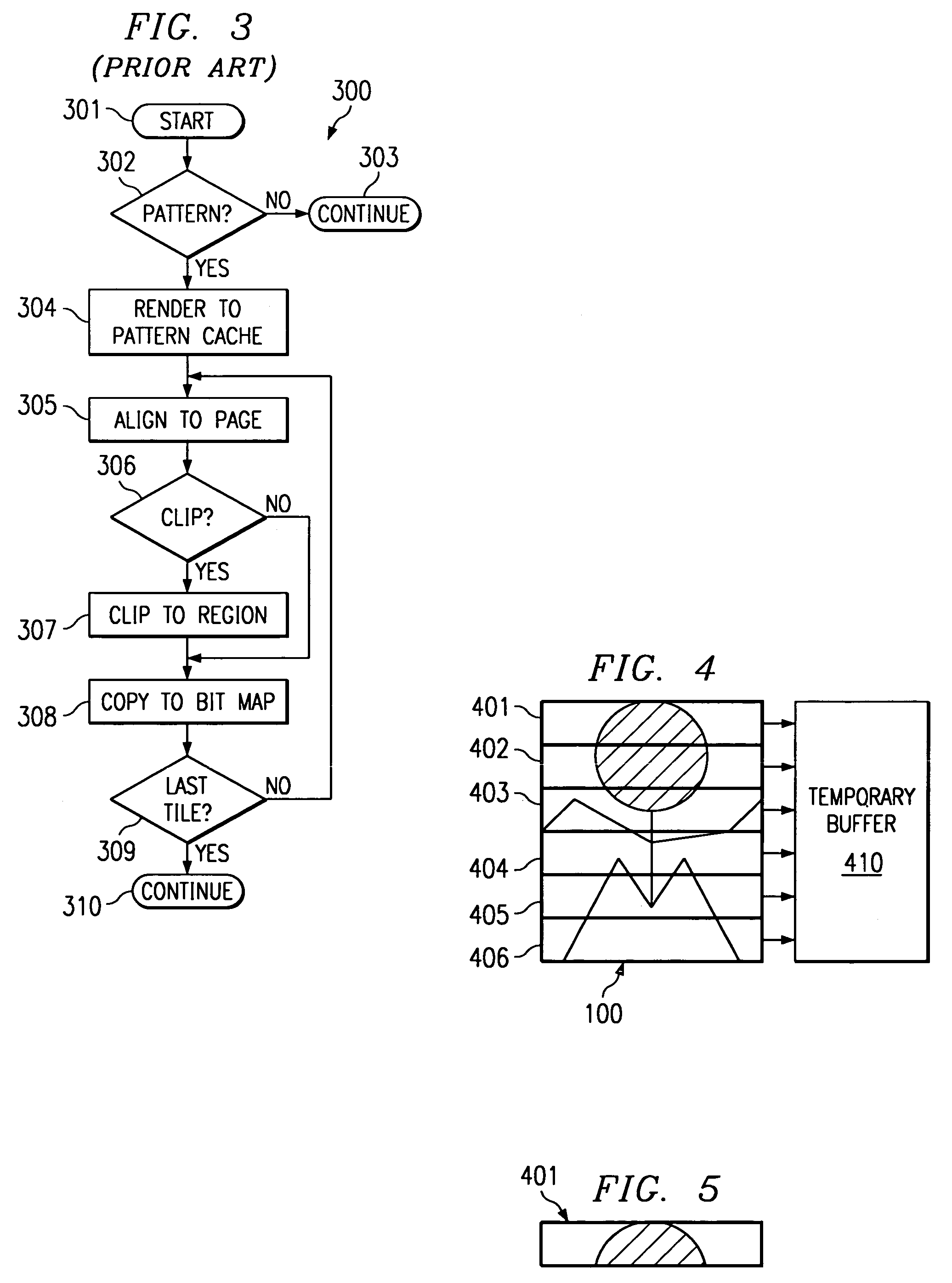
However, storing the image for a large pattern in the pattern cache at high resolutions takes huge amounts of memory.
This requirement of large amounts of memory is disadvantageous.
PostScript printers have traditionally either aborted a printed page upon exceeding the pattern cache capacity or have reverted to some method that was either slow, poor in quality or both.
The interaction between the interpreter and the rendering made it difficult to band the display list and execute in a page pipeline mode where different pages are, simultaneously, in different stages of the conversion from page description language to page bit map.
This limitation is an attempt to avoid the problems of caching large pattern primitives.

Method used


Image

  • Method and apparatus for rendering large patterns in a small memory printer
  • Method and apparatus for rendering large patterns in a small memory printer
  • Method and apparatus for rendering large patterns in a small memory printer

Examples


first embodiment

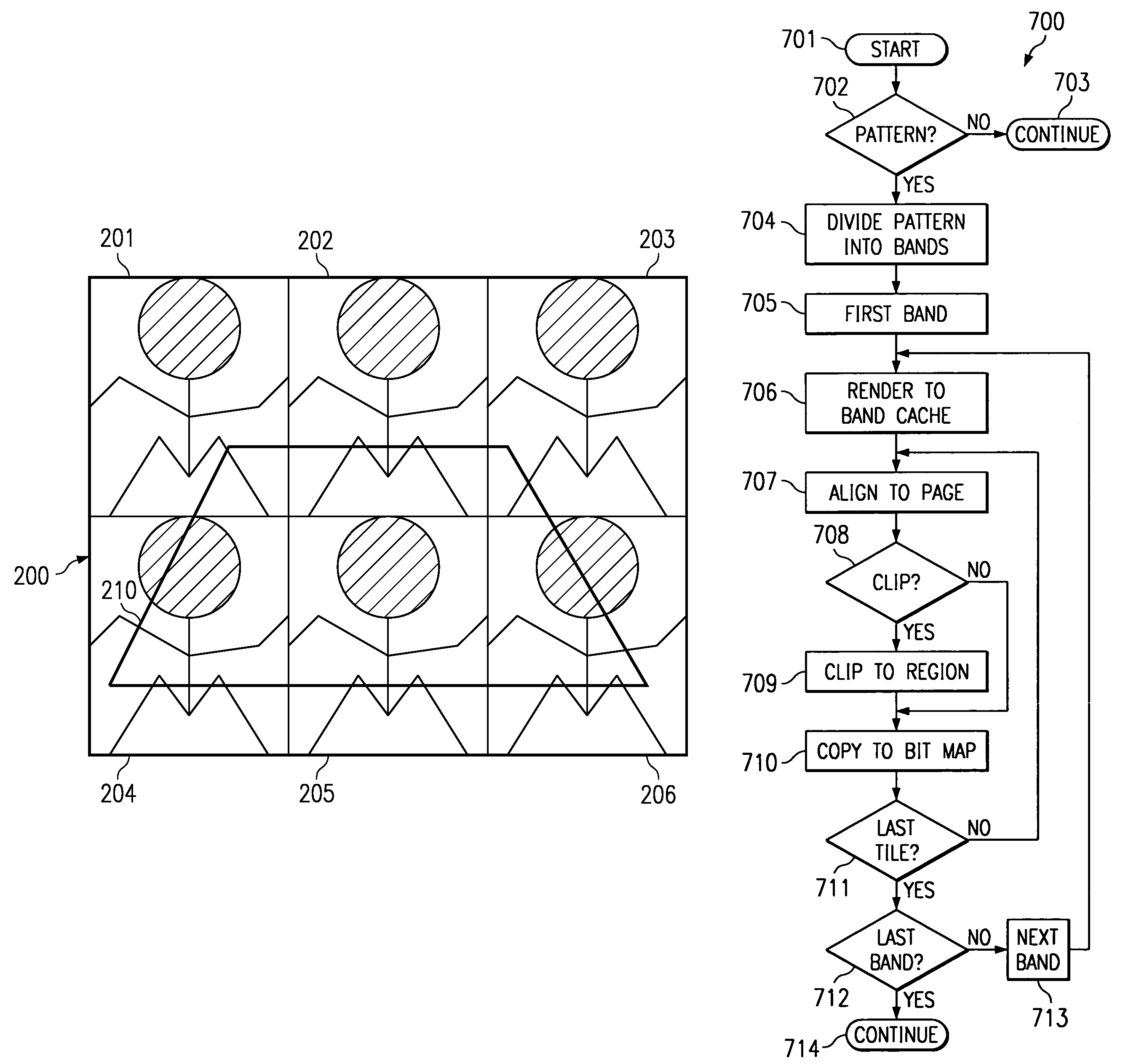
It is necessary to translate these pattern coordinates to page coordinates for the later rendering operation (processing block 807). In a first embodiment, the data processor operating the printer creates a display list element for each tiling of the pattern. This is the easiest to do with a memory extension of the display list interpreter. Upon each instance of processing block 804, subroutine 800 selects the next instance of the pattern display list.

[0050]In a second embodiment, operation of a display list interpreter performing the rendering operation is augmented to include elementary control functions. These new elementary control functions increment the pattern step and call the pattern within loops or nested loops. This second embodiment requires less external memory than the first embodiment because multiple copies of the pattern display list are not required. However, this second embodiment would increase the complexity of the display list interpreter. This will typically r...

third embodiment

[0059]A third embodiment defines a new opcode that consumes the pattern display list. This new opcode has the following format:[0060]Pattern to region opcode[0061]Number of parameters[0062]Pointer to region[0063]Pointer to pattern subroutine

When the display list interpreter encounters the pattern fill display list element, it surrenders control to a surrogate that computes the parameters for each display list element in the pattern subroutine based on the pattern step and clipping region. The surrogate would then“call” the particular opcode in sequences with the parameters passed in the same manner as a normal display list interpreter. The interpreter that builds the display list can make the parameters relative to the pattern step values and the same opcodes can be used for both normal rendering and pattern subroutines.

[0064]FIG. 9 is a block diagram of a network printer system 900 including a multiprocessor integrated circuit 910 constructed for image and graphics processing accor...


PUM


Abstract

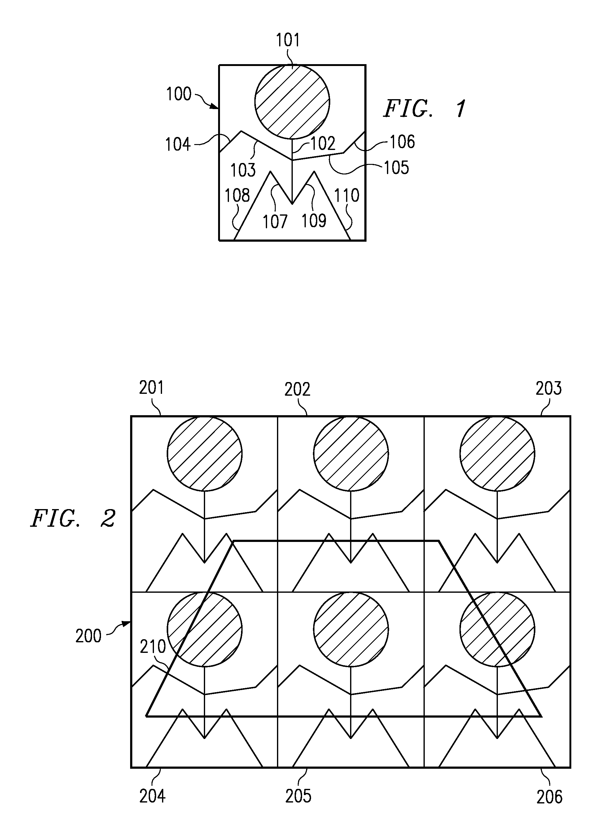
A method of performing a pattern fill operation of a pattern into a clipping region divides dividing the pattern into a plurality of bands. For each band the method renders the band as a bit map into a band cache. For each tiling of the pattern into the clipping region the method clips the bit map of a current band to the clipping region and copies the clipped bit map into a corresponding location of a page bit map. The plurality of bands of the pattern are preferable aligned with scan lines of the printed page. The bands may correspond to individual scan lines. The method select the number of bands so that each band may be stored within a predetermined amount of band cache memory.

Description

TECHNICAL FIELD OF THE INVENTION[0001]The technical field of this invention is printer control and more particularly printer control rendering large patterns with minimal memory.BACKGROUND OF THE INVENTION[0002]A pattern fill operation employs a pattern in a repeating structure to fill a graphics object such as a polygon. In a page description languages like PostScript, patterns are typically reduced to images at the device resolution and stored in a pattern cache for later use to render objects in device space. However, storing the image for a large pattern in the pattern cache at high resolutions takes huge amounts of memory. This requirement of large amounts of memory is disadvantageous.[0003]PostScript printers have traditionally either aborted a printed page upon exceeding the pattern cache capacity or have reverted to some method that was either slow, poor in quality or both. The interaction between the interpreter and the rendering made it difficult to band the display list a...

Claims


Application Information

Patent Timeline
Patent Type & Authority Patents(United States)
IPC IPC(8): G06F15/00G06K9/36H04N1/387G06K15/02
CPCG06K15/1828G06K15/02
Inventor PAYNE, RALPH E.
Owner TEXAS INSTR INC
Learn More