
Sync bursts for frequency offset compensation

a frequency offset and sync burst technology, applied in the field of wireless communication systems, can solve the problems of different frequencies or variations, less accurate and less expensive than crystal-based reference types, and the carrier frequency at which the transmitter and the receiver operate,

Active Publication Date: 2007-10-02
GOOGLE TECHNOLOGY HOLDINGS LLC
View PDF15 Cites 28 Cited by
  • Summary
  • Abstract
  • Description
  • Claims
  • Application Information

AI Technical Summary

Benefits of technology

The present invention provides a way to compensate for the difference in frequency between a transmitter and a receiver. This is done by transmitting multiple bursts of known frequency offset from the carrier frequency, and then the receiver adjusts its own frequency to match the bursts. This helps to mitigate the frequency offset between the two, allowing for better communication between the two devices.

Problems solved by technology

Other types of frequency references, including those constructed of integrated circuit elements such as resistors, inductors and capacitors, tend to be less accurate and less expensive than the crystal-based references.
Even if the transmitter and the receiver reference elements are of similar design, they may produce different frequencies or vary over time due to manufacturing variation and environmental factors such as temperature, vibration, and aging.
This leads to a mismatch between the carrier frequencies at which the transmitter and the receiver operate.
The frequency offset between the transmitter and the receiver is a major hindrance in achieving efficient exchange of data signals between the two devices.
However, the large size and high cost of piezo-electric crystals are undesirable.
The high cost of frequency reference is a limitation especially in low-cost, battery-powered communications equipment designed for sensing and logistics applications.
While the above cited techniques and apparatus deal with the frequency offset problem, the receivers described in these publications require a large bandwidth.
This results in an undesirable degradation in the receiver sensitivity.
While this technique is more efficient in trading the frequency offset tolerance for receiver sensitivity than other techniques, there is a trade-off in the bandwidth of the spread signal that must be applied to mitigate a given amount of frequency offset.
Thus, this technique is limited in its effectiveness in mitigating the frequency offset by the available bandwidth of the signal.
Also, the higher chip rates imply increased power and complexity, which is undesirable in low-cost, battery powered communications hardware.

Method used


Image

  • Sync bursts for frequency offset compensation
  • Sync bursts for frequency offset compensation
  • Sync bursts for frequency offset compensation

Examples


Embodiment Construction

[0025]For convenience, terms that have been used in the description of various embodiments are defined below. It is to be noted that these definitions are given merely to aid the understanding of the description, and that they are, in no way, to be construed as limiting the scope of the invention.

Frequency offset: The difference between the carrier frequencies, at which a transmitter and receiver operate in order to exchange data between themselves, is termed as frequency offset.

Frequency reference: An oscillator that produces a standard frequency for operation of a device is termed as frequency reference.

Time and Frequency Position: The relative position in time and frequency of a frequency synchronization burst with respect to data packets being transmitted and received between devices is termed as time / frequency position of that burst.

Receiver operating frequency: The carrier frequency at which the receiver attempts to receive the transmitted carrier wave is termed as receiver op...


PUM


Abstract

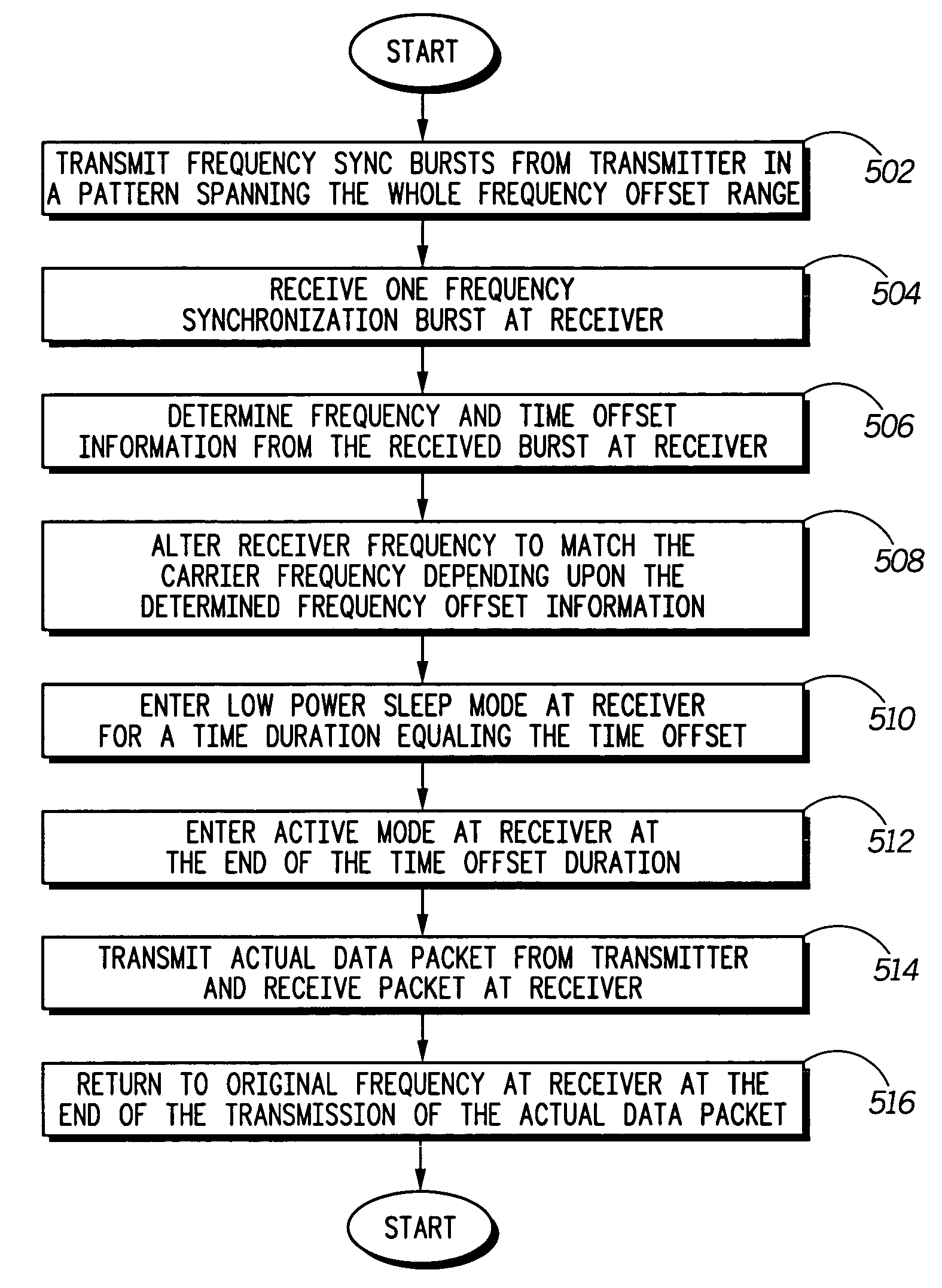
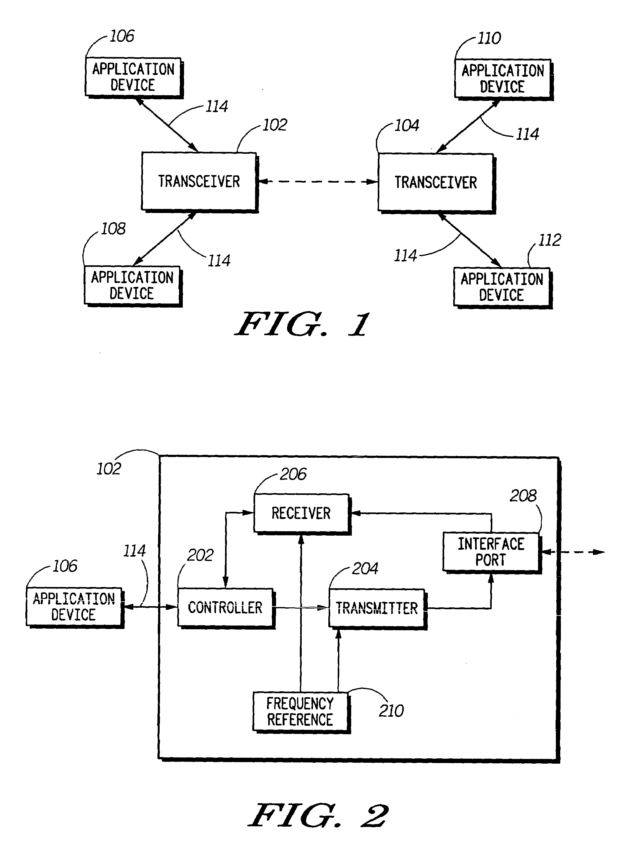
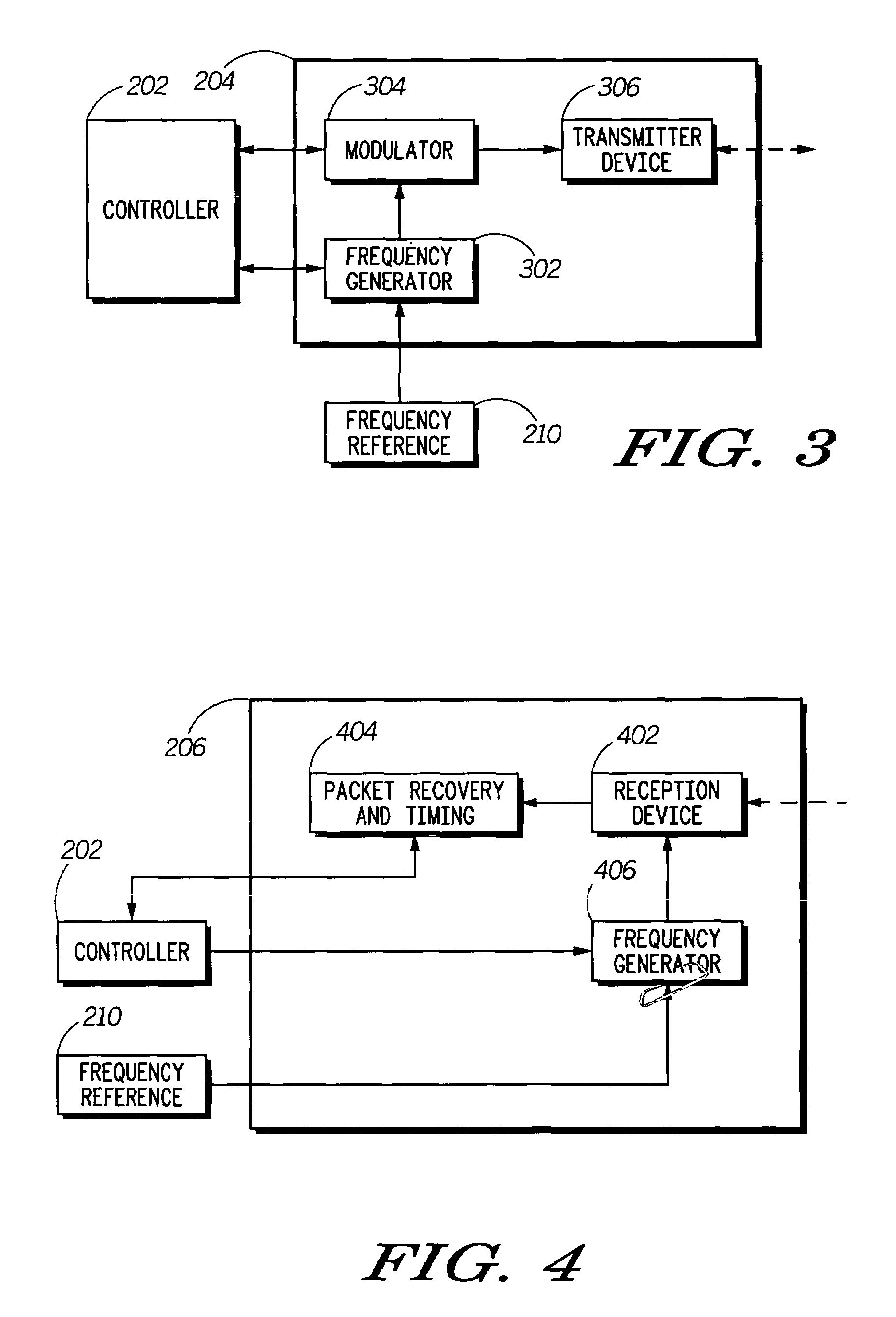
A method (500) and system for compensation of frequency offset between a first transceiver (102) and a second transceiver (104) in wireless communication are disclosed. The compensation of the frequency offset between two or more transceivers (102, 104) is achieved using frequency synchronization bursts. These bursts contain information about the frequency offset. The frequency synchronization bursts are transmitted by the first transceiver at a range of frequencies above and below its carrier frequency (502). A second transceiver that receives at least one of these bursts (504) determines the frequency offset (504), and adjusts its frequency to match the frequency of the first transceiver (508). Thereafter, the second transceiver may enter a low power sleep mode (510) in order to reduce its power consumption. The second transceiver returns to active mode (512) just before the start of the transmission of the data packets (514).

Description

[0001]This invention was made with United States Government support under Agreement No. N66001-03-1-8901 awarded by DARPA. The United States Government has certain rights in the invention. Any opinions, findings, and conclusions or recommendations expressed in this application are those of the authors and do not necessarily reflect the view of the Naval Warfare System Center.FIELD OF THE INVENTION[0002]The present invention relates to wireless communication systems. More particularly, the invention provides a method and system for frequency offset compensation in wireless communication systems. The invention may also be extended to wireline systems employing bandpass communications.BACKGROUND OF THE INVENTION[0003]Over the past few decades, there have been significant advancements in the field of wireless communication. Wireless technology has found applications in a variety of areas such as telephony, control of industrial devices, entertainment and many more. Some common examples ...

Claims


Application Information

Patent Timeline
Patent Type & Authority Patents(United States)
IPC IPC(8): H04J3/06H04B1/18H04B7/005H04J11/00H04J13/00H04LH04L7/04H04L27/00
CPCH04L7/04H04L27/0014H04W56/0035Y02B60/50H04L2027/0083H04L2027/0026Y02D30/70H04L27/26
Inventor GORDAY, PAUL E.CALLAWAY, JR., EDGAR HERBERTMARTIN, FREDERICK L.TAUBENHEIM, DAVID B.
Owner GOOGLE TECHNOLOGY HOLDINGS LLC
Learn More