Moving magnet type linear slider

a magnet-type, linear slider technology, applied in the direction of motor/generator/converter stopper, dynamo-electric converter control, propulsion system, etc., can solve the problem of minute vibration, speed ripple becomes large, and the servo gain cannot be increased

Inactive Publication Date: 2007-10-02
YASKAWA DENKI KK
View PDF3 Cites 7 Cited by
  • Summary
  • Abstract
  • Description
  • Claims
  • Application Information

AI Technical Summary

Benefits of technology

[0013]The preferred embodiments of the present invention have been developed in view of the above-mentioned and / or other problems in the related art. The preferred embodiments of the present invention can significantly improve upon existing methods and / or apparatuses.
[0014]Among other potential advantages, some embodiments can provide a moving magnet type linear slider capable of minimizing the effect of microvibration at the time of the driving, easily increasing the servo gain and suppressing the speed ripple.

Problems solved by technology

In the conventional moving magnet type linear slider, however, since the linear scale 35 is arranged at the one side of the linear slider, the distance L between the thrust central axis G-G of the armature 32 and the central axis S-S at the attachment position of the linear scale 35 is long, causing minute vibrations of the linear scale due to the microvibration of a driven table 3 at the time of controlling the linear motor, which in turn causes such problems that, e.g., the servo gain cannot be increased or the speed ripple becomes large.

Method used


Image

  • Moving magnet type linear slider
  • Moving magnet type linear slider
  • Moving magnet type linear slider

Examples


Embodiment Construction

[0040]In the following paragraphs, some preferred embodiments of the invention will be described by way of example and not limitation. It should be understood based on this disclosure that various other modifications can be made by those in the art based on these illustrated embodiments.

[0041]Hereafter, embodiments of the present invention will be explained with reference to the attached drawings.

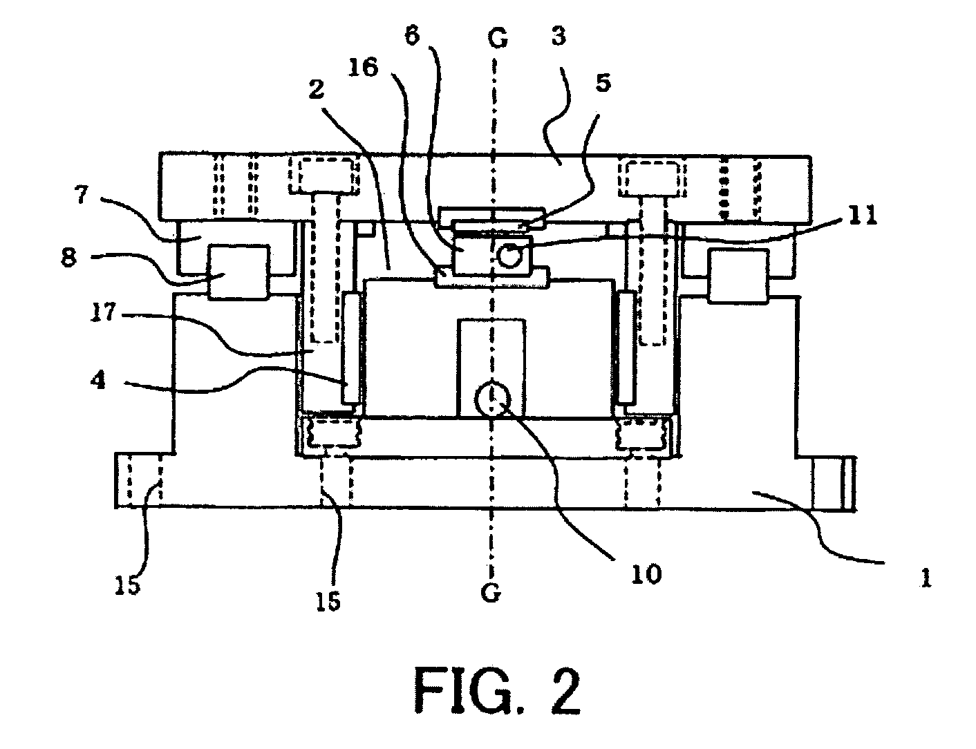
[0042]FIG. 1 is a plan view of a moving magnet type linear slider according to a one embodiment of the present invention, and FIG. 2 is a side view of the linear slider shown in FIG. 1.

[0043]In the drawings, the reference numeral “1” denotes a fixed base, “2” denotes an armature, “3” denotes a table, “4” denotes a field permanent magnet, “5” denotes a linear scale, “6” denotes a sensor head, “7” denotes a slider, “8” denotes a guide rail, “9” denotes a stopper, “10” denotes a motor lead, “11” denotes a linear scale cable lead, “12” denotes a driver, “15” denotes an attachment hole, “16” den...


PUM


Abstract

In some embodiments, a moving magnet type linear slider capable of minimizing the effect of microvibration at the time of driving a linear motor, easily increasing the servo gain and suppressing the speed ripple is provided. The moving magnet type linear slider includes a linear motor for reciprocating a table, and a detector for detecting the relative position of the table and a fixed base. The linear motor includes an armature in which polyphase armature winding is wound around the armature core secured to a fixed base and a field permanent magnet secured to the lower surface of the table in the vertical direction and arranged between the inner side surface of the linear guide and the outside surface of the armature via gaps therebetween. The detector includes a linear scale secured to the lower surface side of the table and a sensor head secured to the upper surface side of the armature, and the central axis of the detector is substantially aligned with the thrust central axis G-G of the armature.

Description

RELATED APPLICATIONS[0001]This application is a continuation-in-part of an International Patent Application No. PCT / JP2005 / 008677, filed on May 12, 2005. This application claims priority under 35 U.S.C. §119 to Japanese Patent Application No. 2004-173841 filed on Jun. 11, 2004. Each of the entire disclosures of these applications is incorporated herein by reference in its entirety.BACKGROUND OF THE INVENTION[0002]1. Field of the Invention[0003]The present invention relates to a linear motor for use in various industrial machinery, such as, e.g., electrical component mounting apparatuses, semiconductor related apparatuses, or machine tools, and suitably used for driving the direct acting mechanism thereof, and more specifically to a moving magnet type linear slider of a suction force offset type equipped with a field permanent magnet as a moving unit and an armature having an armature winding as a stator.[0004]2. Description of Related Art[0005]The following description sets forth th...

Claims


Application Information

Patent Timeline
Patent Type & Authority Patents(United States)
IPC IPC(8): H02K41/00G01D5/12H02K11/00H02K41/02H02K41/03H02P7/00H02P25/06
CPCH02P25/06H02K41/03H02K11/00H02K41/00
Inventor MIYAMOTO, YASUHIRO
Owner YASKAWA DENKI KK
Why Eureka
Try Eureka