
Intelligent lift interlock system

a technology of intelligent lifting and interlocking, applied in the field of microprocessor-based systems, can solve the problem of not addressing the use of parking brakes, and achieve the effect of eliminating excessive parking brake wear and preventing or reducing injuries

Inactive Publication Date: 2007-09-25
INTERMOTIVE
View PDF34 Cites 19 Cited by
  • Summary
  • Abstract
  • Description
  • Claims
  • Application Information

AI Technical Summary

Benefits of technology

"The present invention is an intelligent lift interlock system that prevents a vehicle from being moved when an auxiliary device is operated. The system uses sensors and a microprocessor to determine if the vehicle is in park and if all the necessary conditions are met for safely activating the lift device. This prevents accidents and reduces wear and tear on the vehicle's parking brake. The system can be installed as original equipment or added at a later time and includes a diagnostic display and dedicated park output for safely exiting or entering the vehicle."

Problems solved by technology

This patent, however, does not address the use of a parking brake or lift door input as parameters which are also helpful in ensuring that the vehicle will not operate while the lift apparatus is being used.

Method used


Image

  • Intelligent lift interlock system
  • Intelligent lift interlock system
  • Intelligent lift interlock system

Examples


Embodiment Construction

[0015]Various aspects of the present invention will evolve from the following detailed description of the preferred embodiments thereof which should be referenced to the prior described drawings.

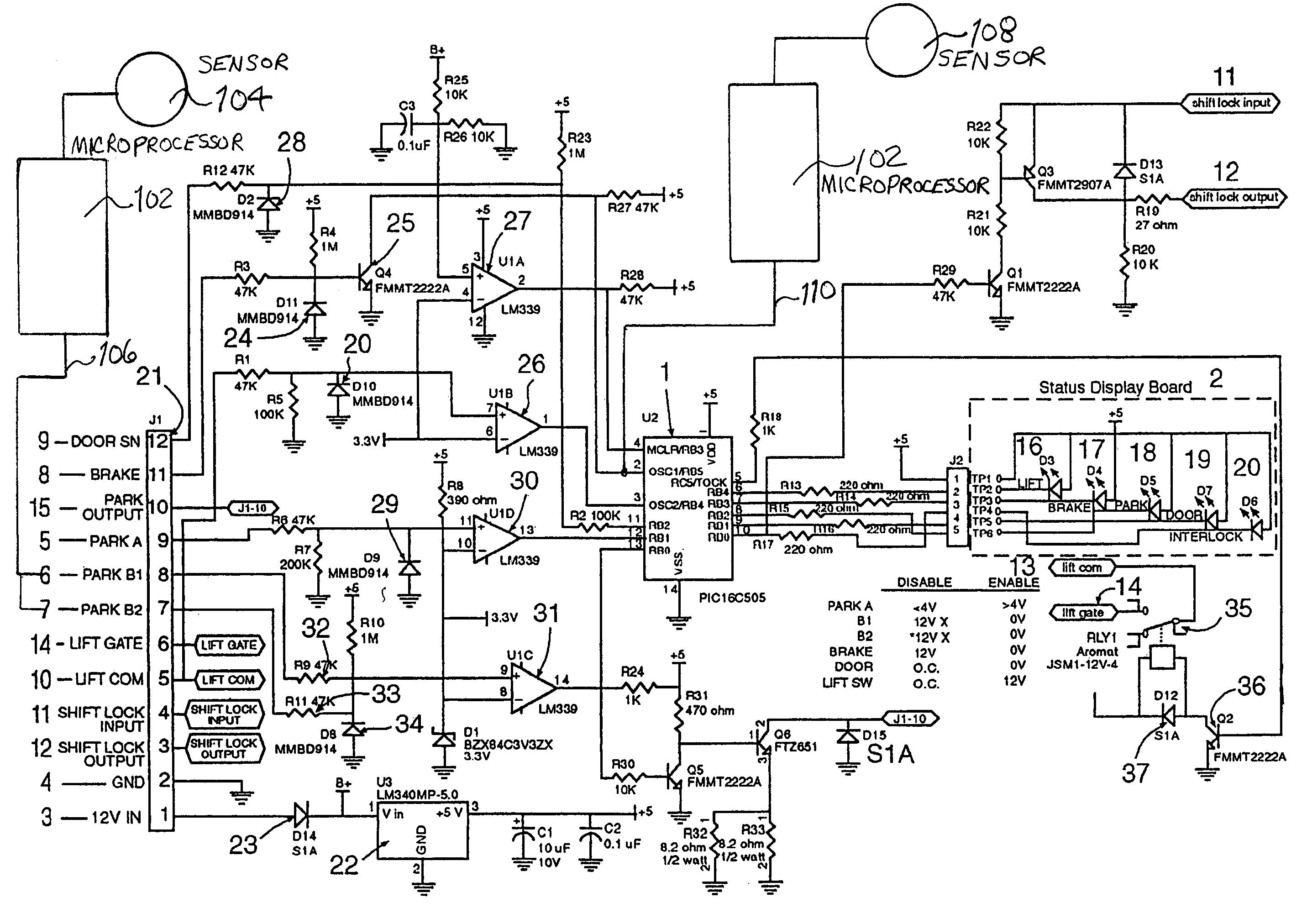
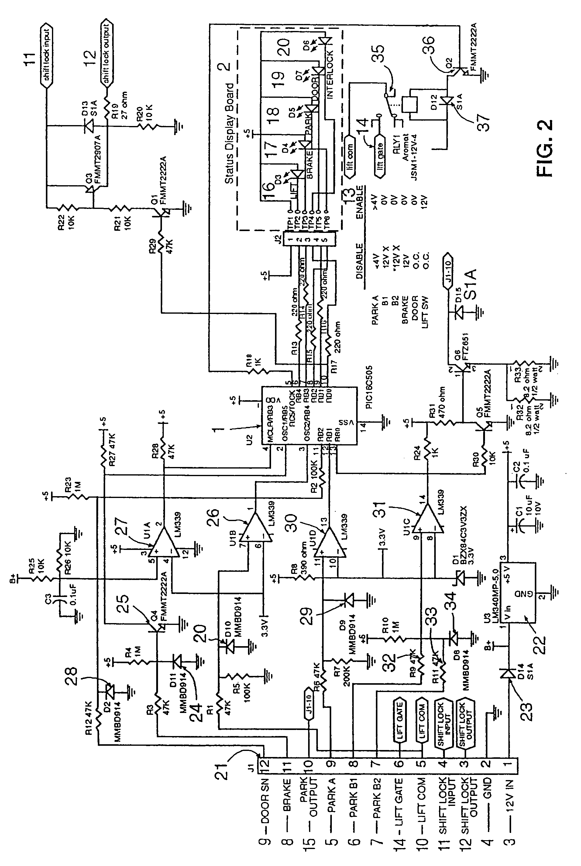
[0016]FIG. 1 illustrates the various inputs received by a microprocessor 1 as well as the various outputs transmitted from the microprocessor 1. Although various types of microprocessors can be utilized, the present invention preferably employs a microchip PIC 16c505 microprocessor. This particular microprocessor contains fourteen (14) available input or output pins utilized to practice the present invention. The input lines shown on the left hand side of FIG. 1 include a power line 3, a ground line 4, an analog transmission-park signal 5, two digital transmission-park signals 6, 7, a parking brake signal 8, a lift door “open” switch 9, a lift power toggle switch 10, a shift lock solenoid (in circuit 11), and a lift power-in circuit 13.

[0017]Various outputs are provided from the microprocess...


PUM


Abstract

A microprocessor controlled system for ensuring the safe operation of an auxiliary device, such as a wheelchair lift used in conjunction with a vehicle. The microprocessor preferably allows operation of the lift device when one or more parameters are met. These parameters include the following: the vehicle is in “park”, the parking brake is engaged, the vehicle ignition is “on”, the lift power switch is “on”, and the lift door is open. The present invention does not allow the vehicle to be shifted out of park if the lift door is open and / or when the parking brake is “on”.

Description

CROSS-REFERENCES TO RELATED APPLICATIONS[0001]The present application is a continuation-in-part of U.S. patent application Ser. No. 10 / 613,336, filed 3 Jul. 2003, now issued as U.S. Pat. No. 6,965,819 on 15 Nov. 2005; which is a continuation of U.S. patent application Ser. No. 09 / 904,834, filed 16 Jul. 2001, now issued as U.S. Pat. No. 6,594,565 on 15 Jul. 2003, which claims the benefit of the filing date of U.S. Provisional Patent Application 60 / 218,534, filed on 17 Jul. 2000.FIELD OF THE INVENTION[0002]The present invention is directed to a microprocessor-based system for use in a vehicle for controlling the operation of various auxiliary devices, such as wheelchair lifts, lift gates, personal lifts, or any other device that requires activation with the vehicle in a secure position.BACKGROUND OF THE INVENTION[0003]In the last several years, we have witnessed the increased use of various auxiliary lift devices, such as wheelchair lifts, lift gates and personal lifts, which are used...

Claims


Application Information

Patent Timeline
Patent Type & Authority Patents(United States)
IPC IPC(8): A61G3/00A61G3/06B60P1/44
CPCB60P1/4471A61G3/062A61G2220/16
Inventor SCHAFER, GREGORY E.PROKOPIK, EDWARD J.
Owner INTERMOTIVE
Learn More