
Disk device and disk access route mapping

a technology of access route and disk device, applied in the field of storage technique, can solve the problems of large amount of time required for the server's start or recognition of disk devices, server may become inoperable, etc., and achieve the effect of efficiently accessing the necessary disk devices

Inactive Publication Date: 2007-09-18
HITACHI LTD
View PDF10 Cites 15 Cited by
  • Summary
  • Abstract
  • Description
  • Claims
  • Application Information

AI Technical Summary

Benefits of technology

[0005]An object of the present invention is to achieve reduction in time for server's recognition of disk devices and avoidance of an error such as failure in starting caused by recognition of unnecessary disk devices in a storage area network system.
[0006]Another object of the invention is to provide a switch and an information processing system, in which when connection of a disk subsystem in a storage area network system is changed, a change of a route to a changed disk storage can be achieved without interruption of any access operation in the system.
[0008]More specifically, in a system having a storage area network environment in which a large number of disk devices are present in each of storage subsystems connected to one another through an information network, disk devices and access route mapping used by each of servers are unitarily managed as management information common to the storage subsystems, the disk devices, fiber channel switches and the servers by a part (specific dedicated disk device) of each of the storage subsystems. When the respective devices in the system acquire the management information and use it as control information, each of the servers can access necessary disk devices efficiently.

Problems solved by technology

In the system having a storage area network environment in which a large number of disk devices are present, when a server starts or when a server executes a disk device recognition process, a large amount of time may be required for the server's start or recognition of disk devices because the server also has to recognize disk devices not intended to be used by the server.
Moreover, because the number of disk devices that can be recognized by the server is limited in accordance with the capacity and performance of the server or of an operating system of the server, the server may become inoperative when the number of the all disk devices exceeds the limit.

Method used


Image

  • Disk device and disk access route mapping
  • Disk device and disk access route mapping
  • Disk device and disk access route mapping

Examples


Embodiment Construction

[0016]An embodiment of the present invention will be described in detail below with reference to the drawings.

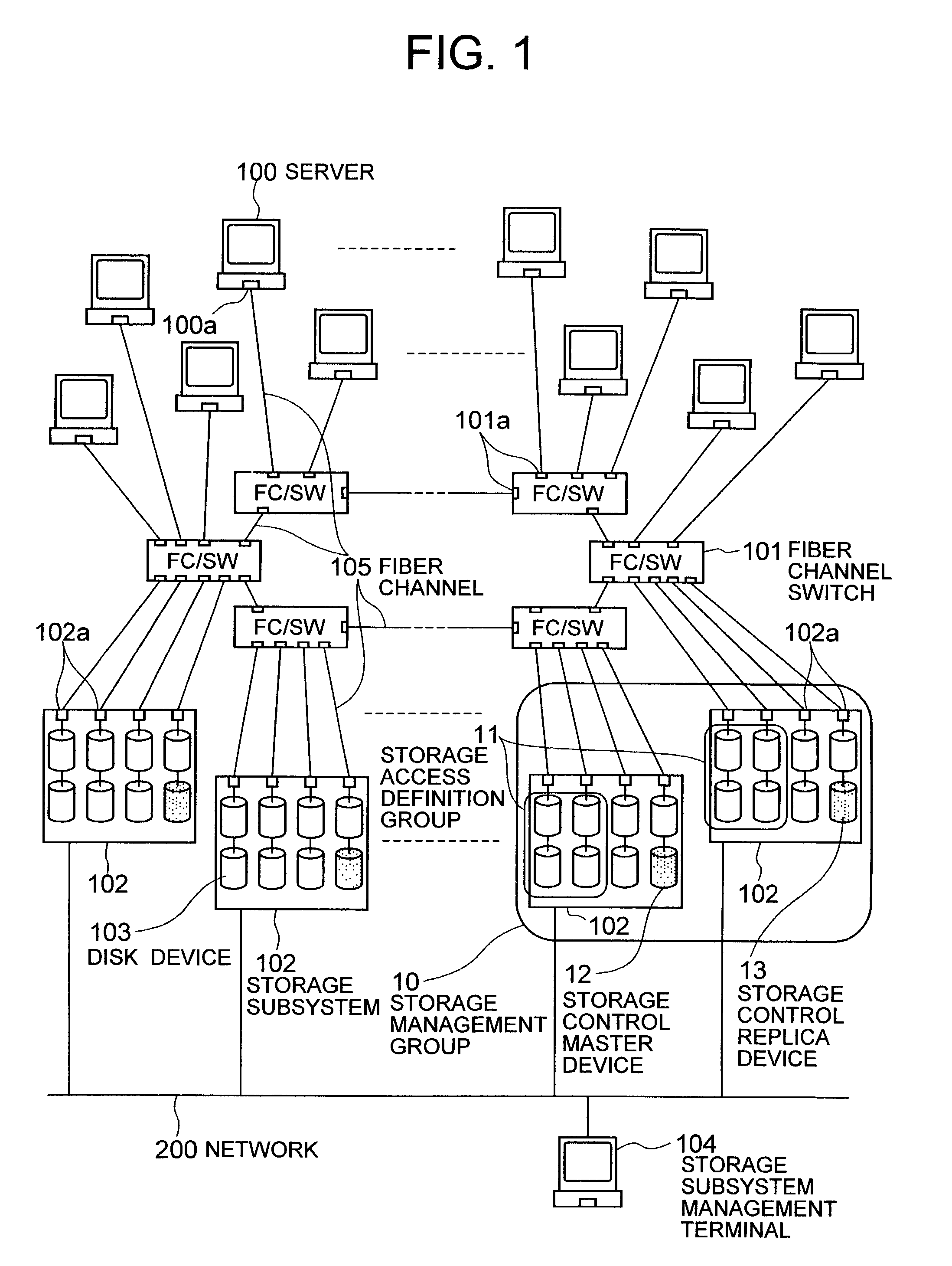
[0017]FIG. 1 is a conceptual view showing an example of the configuration of an information processing system including a storage area network system in which a control method according to an embodiment of the present invention is carried out.

[0018]The information processing system according to this embodiment is constituted by a storage area network system, and a large number of servers 100. The storage area network system includes a large number of fiber channel switches 101, and a large number of storage systems or storage subsystems 102. Each of the storage subsystems 102 has a large number (e.g. several thousands or more) of disk devices 103 such as physical volumes, physical disk devices, logical volumes or logical disk devices (LU). The servers 100 are connected to the storage area network system through the fiber channel switches 101.

[0019]The servers 100 are connect...


PUM


Abstract

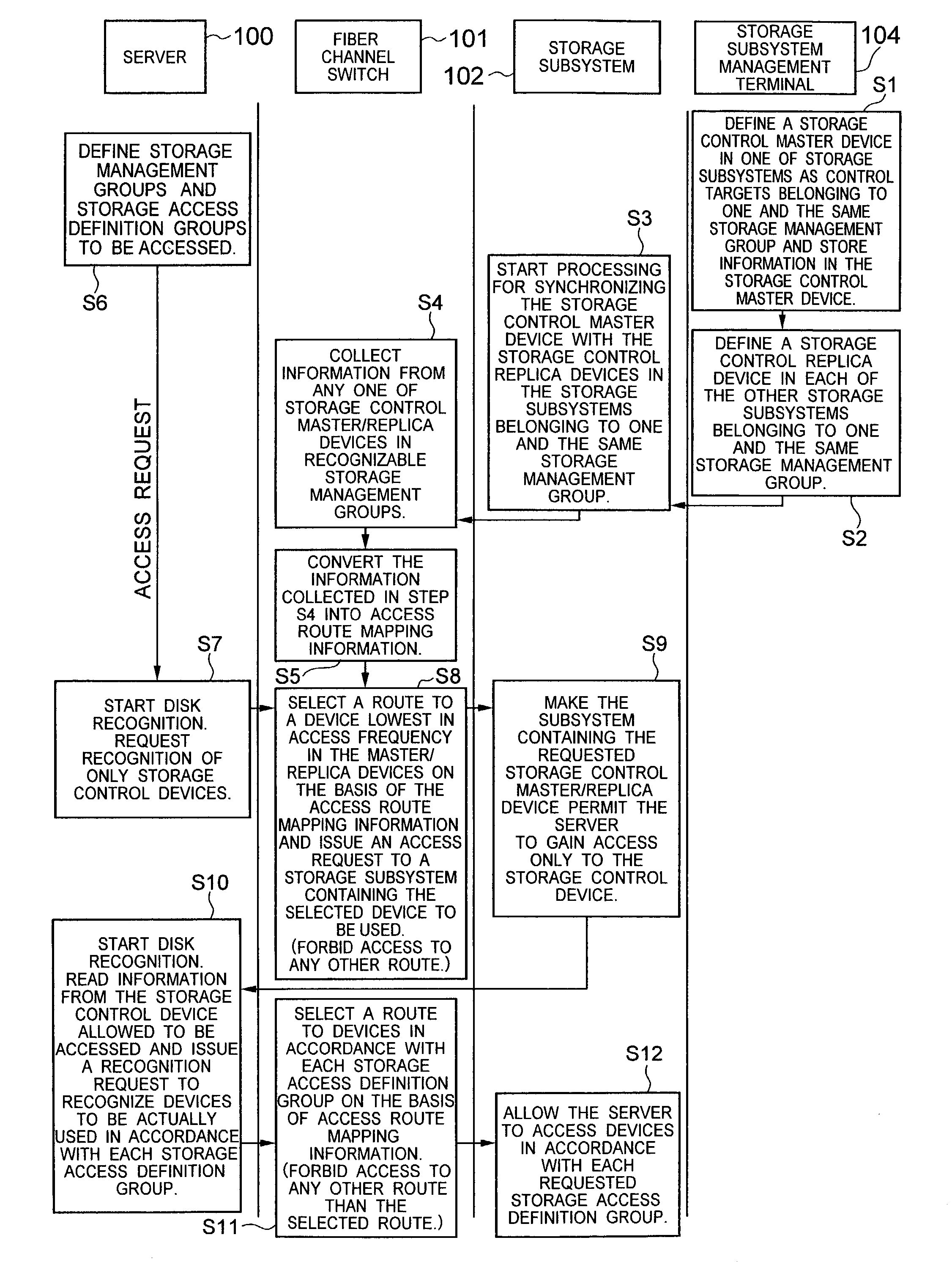
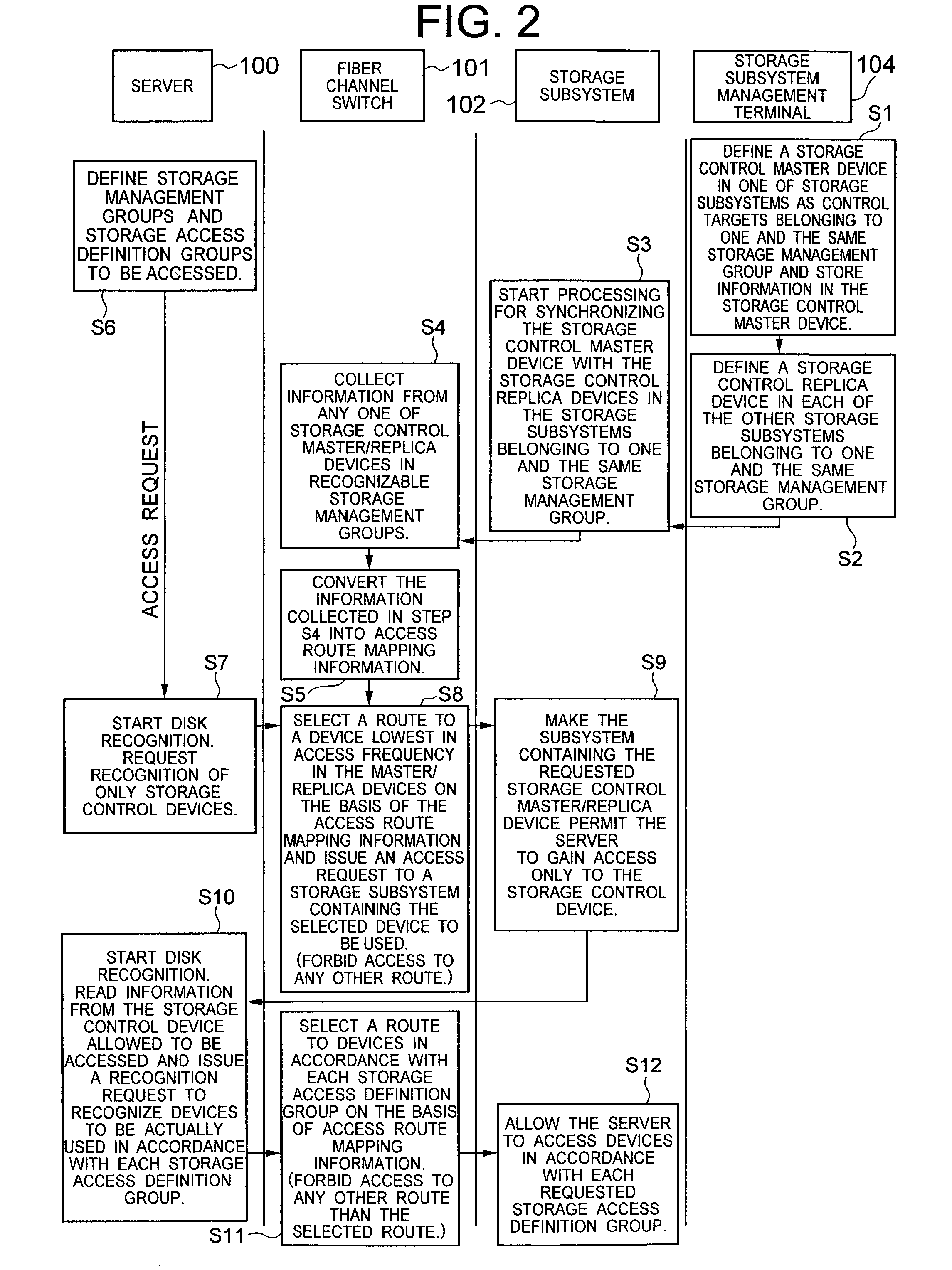
In a storage area network system in which storage subsystems each containing disk devices are connected to servers through fiber channels and fiber channel switches, one of disk devices in each of the storage subsystems is used as either a storage control master device or a storage control replica device in which group setting information concerning classification of disk devices into a storage management group and a storage access definition group or storage access definition groups is stored. When a server starts, the server is made to selectively recognize the storage control master device or the storage control replica device, to read the group setting information from the recognized storage control device, and further to recognize only disk devices belonging to a group in association with the server.

Description

BACKGROUND OF THE INVENTION[0001]The present invention relates to a storage technique, particularly to management and control of storage devices in a computer system and more specifically to an effective technique applied to a storage area network system including storage device-containing storage subsystems, fiber channel switches, and servers.[0002]Increase in scale and capacity of data storage devices for various kinds of databases or WEB servers has been advanced with the development of information-oriented society such as popularization of the Internet. The concept “storage area network system” is known as a configuration used in place of a conventional configuration in which private storage subsystems are connected to one host so as to be subordinate to the host. In the storage area network system, a plurality of storage subsystems are connected to one another through a private information network to thereby logically construct one huge storage device in a state in which a plu...

Claims


Application Information

Patent Timeline
IPC IPC(8): G06F13/00G06F13/10G06F3/06G06F13/14G06F15/173H04L29/08
CPCG06F3/0613G06F3/0632G06F3/0635G06F3/067H04L67/1097
Inventor SATO, EIICHI
Owner HITACHI LTD
Learn More